EXPLANATION OF COMPONENTS
The following is an explanation of devices necessary to operate the machine.
To perform suitable operations correctly and safely, it is important to completely understand methods of operat-
ing the equipment, and the meanings of the displays.
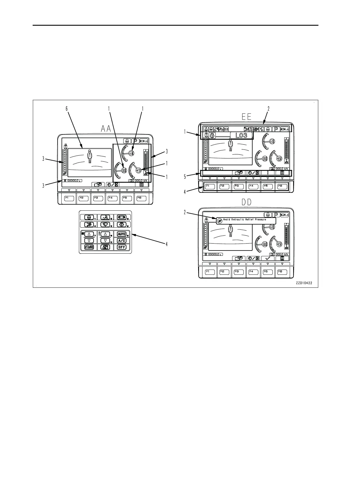
EXPLANATION OF MACHINE MONITOR EQUIPMENT
AA: Standard screen, EE: Warning or Error screen, DD: Guidance screen
(1) Warning display
(2) Pilot display
(3) Meter display
(4) Monitor switch area
(5) Guidance icon display
(6) Camera image display
REMARK
• For the user menu used for setting various items of the machine on the machine monitor, see “USER
MENU DISPLAY SWITCH (3-57)”.
• One of the features of liquid crystal display panels is that there may be black spots (spots that do not light
up) or white spots (spots that stay lit) on the screen. When there are fewer than 10 black or white spots, this
is not a failure or a defect.
• If environmental temperature of the machine monitor is high, brightness may be automatically reduced to
protect the liquid crystal. However, it is not abnormal.
When displaying only meter
On the standard screen (for camera display and meter display), you can shift the display to only the meter dis-
play by pressing switch F3.
OPERATION EXPLANATION OF COMPONENTS
3-9

 Loading...