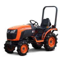
one of the holes on the inner bar, both stabilizers will be
locked.
If the set-pin is inserted through the slot to engage one
of the holes on the inner bar, a limited degree of sway
will be permitted.
(1) Outer tube
(2) Inner bar
(3) Set-pin
(4) Hole
(5) Slot
DRAWBAR
WARNING
To avoid personal injury or death:
• Never pull from the top link, the rear axle or any
point above the drawbar. Doing so could cause
the tractor to tip over rearward causing
personal injury or death.
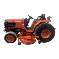
1. Adjusting drawbar length
When towing an implement, use of (B) hole in drawbar
is recommended.
The acceptable drawbar load is provided in
IMPLEMENT LIMITATIONS on page 21.
(1) PTO shaft cap
(2) Drawbar
(3) Drawbar pin
(A) Hole
(B) Hole
3-POINT HITCH AND DRAWBAR DRAWBAR
B2401DT, B2401DTWO, B2401DTN
 Loading...