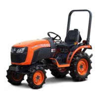
[B2401DTWO / B2401DTN only]
(1) Block cover
(2) Block cover outlet (option)
(3) Outlet
(4) Inlet
(5) Hydraulic block
(A) When implement is not at-
tached.
(B) When implement is attached.
(C) From gear pump
(D) To implement inlet (no relief
valve in the hydraulic block)
(E) From implement outlet
(D)
Max. flow
17.9 L/min
(4.7 U.S.gals./min)
IMPORTANT :
• For hydraulic block type outlet, be sure to use
the control valve of the [power beyond type]
with relief valve that has a third line return to
tank for the operation of hydraulic block.
NOTE :
• The "tank" port flow from implement valve
should be connected to the port located on the
right hand side of transmission case.
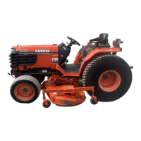
(1) Return port
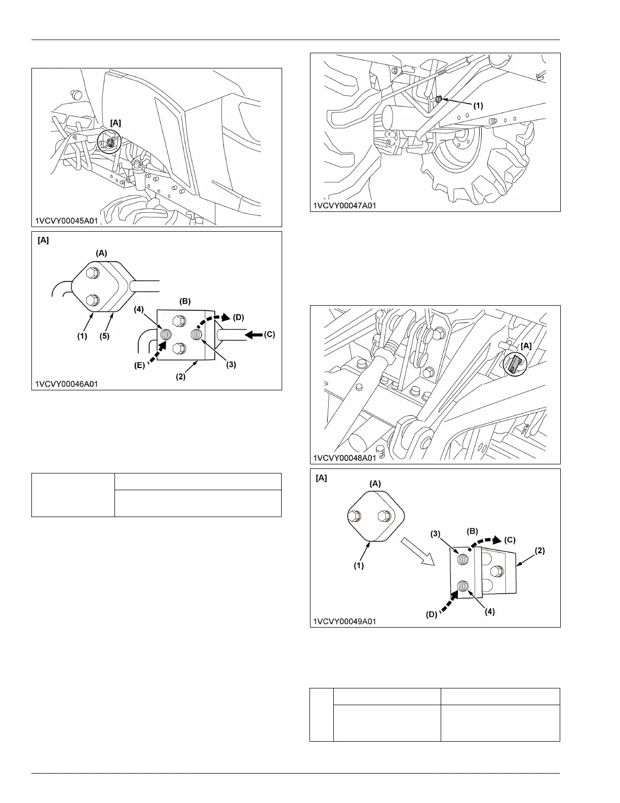
1.1 Rear outlet
[All models]
2-hydraulic outlets are provided on the tractor.
(1) Block cover
(2) Block cover outlet (option)
(3) Outlet
(4) Inlet
(A) When implement is not at-
tached.
(B) When implement is attached.
(C) To implement inlet
(D) From implement outlet
(C)
Max. flow Max. pressure
16.6 L/min
(4.4 U.S.gals./min)
13.2 MPa to 13.7 MPa
(135 kgf/cm
2
to 140 kgf/cm
2
)
[1920 psi to 1992 psi]
HYDRAULIC UNIT AUXILIARY HYDRAULICS
B2401DT, B2401DTWO, B2401DTN
 Loading...