Paragraphs 25-26
KUBOTA
Compression release
position
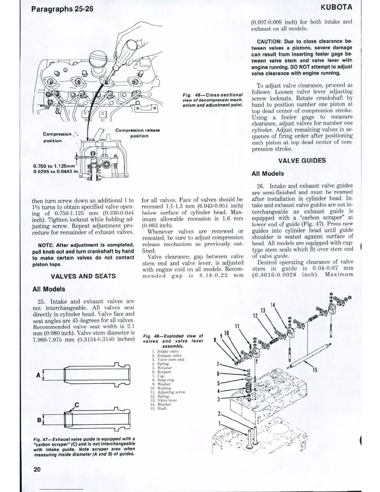
Ftg. 46—Cross-sectional
view of decompressor mech-
anism and adjustment point
0.750 to 1.125mm
0.0295 to 0.0443 in.
then turn screw down an additional
1
to
IV2 turns to obtain specified valve open-
ing of 0.750-1.125 mm (0.030-0.044
inch).
Tighten locknut while holding ad-
justing screw. Repeat adjustment pro-
cedure for remainder of exhaust valves.
NOTE:
After adjustment is completed,
puil knob out and turn cranlcshaft by hand
to make certain valves do not contact
piston tops.
VALVES AND SEATS
All Models
25.
Intake and exhaust valves are
not interchangeable. All valves seat
directly in cylinder head. Valve face and
seat angles are 45 degrees for all valves.
Recommended valve seat width is 2.1
mm (0.080 inch). Valve stem diameter is
7.960-7.975 mm (0.3134-0.3140 inches)
t
for all valves. Face of valves should be
recessed
1.1-1.3
mm (0.043-0.051 inch)
below surface of cylinder head. Max-
imum allowable recession is 1.6 mm
(0.063 inch).
Whenever valves are renewed or
reseated, be sure to adjust compression
release mechanism as previously out-
lined.
Valve clearance, gap between valve
stem end and valve lever, is adjusted
with engine cold on all models. Recom-
mended gap is 0.18-0.22 mm
(0.007-0.009 inch) for both intake and
exhaust on all models.
CAUTION:
Due to close ciearance be-
tween valves a pistons, severe damage
can resuit from inserting feeler gage be-
tween vaive stem and vaive iever with
engine running. DO NOT attempt to adjust
vaive clearance with engine running.
To adjust valve clearance, proceed as
follows: Loosen valve lever adjusting
screw locknuts. Rotate crankshaft by
hand to position number one piston at
top dead center of compression stroke.
Using a feeler gage to measure
clearance, adjust valves for number one
cylinder. Adjust remaining valves in se-
quence of firing order after positioning
each piston at top dead center of com-
pression stroke.
VALVE GUIDES
All Models
26.
Intake and exhaust valve guides
are semi-finished and must be reamed
after installation in cylinder head. In-
take and exhaust valve guides are not in-
terchangeable as exhaust guide is
equipped with a "carbon scraper" at
lower end of guide (Fig. 47). Press new
guides into cylinder head until guide
shoulder is seated against surface of
head. All models are equipped with cup-
type stem seals which fit over stem end
of valve guide.
Desired operating clearance of valve
stem in guide is 0.04-0.07 mm
(0.0016-0.0028 inch). Maximum
14
Fig. 48—Exploded vtew of
valves and valve lever
assembly.
1.
Intake valve
2.
Exhaust valve
3.
Valve stem seal
4.
Spring
5.
Retainer
6. Keepers
7.
Cap
8. Snap ring
9. Washer
10.
Bushing
11.
Adjusting screw
12.
Spring
13.
Valve lever
14.
Bracket
15.
Shaft
10
Fig. 47—Exhaust valve guide is equipped with a
"carbon scraper" (C) and is not interchangeable
with Intake guide. Note scraper area when
measuring inside diameter
(A
and B) of guides.
20
 Loading...