SHOP MANUAL
Paragraphs 53-58
emerging
in a
straight axis fronni nozzle
tip.
If pattern is wet, ragged or intermit-
tent, nozzle must
be
overhauled
or
renewed.
53.
OVERHAUL. Hard
or
sharp
tools,
emery cloth, wire brush
or
grin-
ding compound must never be used. An
approved nozzle cleaning kit is available
through
a
number of specialized sources.
Wipe all dirt and loose carbon from ex-
terior
of
nozzle assembly. Secure nozzle
in
a
soft-jawed vise
or
holding fixture
and remove nozzle
nut
(10-Fig.
63).
Carefully separate parts
and
place
in
clean calibrating oil or diesel fuel as they
are removed.
Be
sure parts from each
injector are kept together and separate
from other units.
Clean exterior surfaces with
a
brass
wire brush, soaking in an approved car-
bon solvent,
if
necessary, to loosen hard
carbon deposits. Rinse parts
in
clean
diesel fuel immediately after cleaning to
neutralize the solvent and prevent etch-
ing
of
polished surfaces.
Clean nozzle spray hole from inside us-
ing
a
pointed hardwood stick. Scrape
carbon from pressure chamber using
hooked scraper. Clean valve seat using
brass scraper. Reclean all parts by rins-
ing
in
clean diesel fuel. Check nozzle
fit
by holding nozzle body vertically and lift-
ing needle valve
up
about
V3 of its
length, then release needle. Needle must
slide to its seat by its own weight.
If
nee-
dle movement is rough or sticky, reclean
or renew nozzle valve assembly
as
necessary.
Reassemble injector while parts
are
immersed
in
diesel fuel
to
avoid
con-
tamination. Make sure pressure
ad-
justing shim (5) is in place. Tighten noz-
zle nut
to a
torque
of
59-78 N-m (44-58
ft.-lbs.).
Do not overtighten as distortion
may cause nozzle valve
to
stick and
no
amount
of
overtightening
can
stop
a
leak caused by scratches
or
dirt. Retest
injector
as
previously outlined.
GLOW PLUGS
All Models
54.
One
glow plug
is
provided
in
precombustion chamber
of
each
cylinder.
To
check glow plugs, discon-
nect wiring cable from glow plug
ter-
minal, then connect an ohmmeter across
glow plug terminal and body. Resistance
should
be
approximately
1.5
ohms.
If
resistance
is
zero ohms, glow plug
is
shorted.
If
resistance is infinite, an open
circuit exists
in
glow plug.
COOLING
SYSTEM
55.
All models use a pressurized cool-
ing system which raises coolant boiling
point. All models except LI85 use an im-
peller type centrifugal pump
to
provide
forced coolant circulation
and a
ther-
mostat
to
stabilize o pera tin g
temperature.
Model LI85 uses natural circulation in
which
the
relative density
of hot and
cold liquid provides the means of coolant
circulation.
No
coolant pump
or
ther-
mostat is used in this system.
It
is
of
ut-
most importance that coolant level
be
maintained
at a
level which fully covers
upper coolant hose inlet elbow.
RADIATOR
All Models
56.
Radiator cap pressure valve is set
to open
at 88.3 kPa
(12.8
psi) on all
models. Some models are equipped with
a whistle-type warning device attached
to radiator overflow pipe. Make sure
whistle
is
operative
and
properly
con-
nected
to
radiator.
To remove radiator, first drain coolant
and remove hood. Disconnect radiator
hoses
and air
cleaner hose. Remove
mounting cap screws, then lift radiator
from tractor.
THERMOSTAT
All Models Except L185
57.
On
models
so
equipped,
the by-
pass type thermostat
is
located
in
coolant outlet elbow. Thermostat should
begin to open at about 82°C (180°F) and
be fully open
at
95°C (203°F).
WATER PUMP
All Models Except L185
58.
R&R AND OVERHAUL. Refer
to appropriate Fig. 64, 65
or
66
for an
exploded view
of
water pump.
To
remove pump, drain cooling system and
remove radiator,
if
necessary, for access
to pump. Remove
fan
belt, then unbolt
and remove water pump.
To disassemble pump, remove
fan
pulley using
a
suitable puller. Unseat
pump shaft bearing front retaining ring,
then press shaft
and
bearings forward
out
of
impeller and pump body. Remove
seal assembly from pump body.
All water pump parts are available in-
dividually. To reassemble pump, reverse
the disassembly procedure.
On
pumps
equipped with
fan
pulley retaining nut,
tighten
nut to a
torque
of
70-78
N-m
(50-58 ft.-lbs.).
in
L^Lli
111
I
1
I
1
r
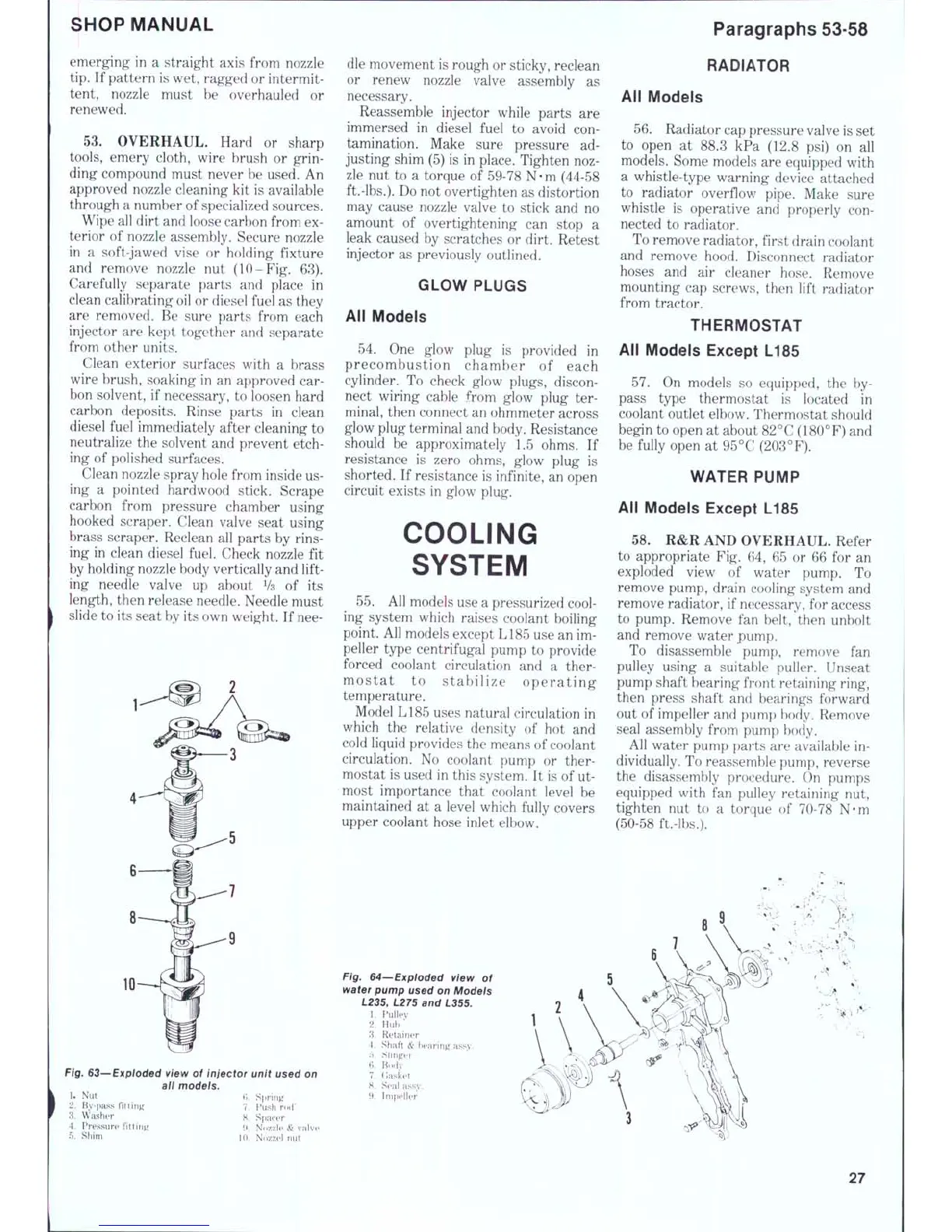
Fig. G3—Exploded view of injector unit used on
all models.
1.
Nut
2. Bv-pass
fittin^^
•S.
Washer
4.
Pressure
fittin^^
5. Shim
H Snrinti
1.
Push
nKf
8. Spacer
iK Nozzle
&
valve
U).
N(»zzel
nut
F/g. 64~-Exploded view of
water pump used on Models
L235, L275 and L355.
1.
Pulley
2.
Hub
*
3. Retainer
•1.
Shaft
&
bearinj^ a.ssy.
B.' Bndy
7. (iHsket
H. Seal assv.
9. Impeller
27
 Loading...