SHOP MANUAL
Paragraph 61
Bulb
Fig. 71—To check reguiator cut-in voltage, con-
nect voltmeter to N terminal as shown and in-
staii a 30W bulb in place of 10A fuse.
minal and ground (Fig. 71). Remove lOA
fuse (connecting red wires) from fuse
panel and connect a 30W bulb in its
place. Start engine and increase speed
until charge indicator lamp goes off or
dims.
At this point, voltage reading
should be 4.5-5.8 volts. If cut-in voltage
is too high, bend voltage relay adjusting
arm (4-Fig. 72) closer to coil. If cut-in
voltage is low, bend adjusting arm away
from coil.
To check no-load regulating voltage,
connect voltmeter across B terminal and
ground (Fig. 73). Start engine and
operate above 1300 rpm, then discon-
nect battery ground cable. Increase
engine speed to obtain maximum
Fig. 72—Cut in voitage can be adjusted by
bend-
ing voitage relay adjusting arm (4). Bend voltage
regulator adjusting arm (2) to adjust regulated
voltage.
1,
Voltage regulator
2.
Adjusting
arm
;i.
Voltage relay
4,
Aiijustin^^ arm
22
3
1
12
14
16
20
21
Fig. 74—Exploded view of typicai alternator used on aii models.
1.
Nut
2.
Lockwasher
3.
Spacer
4.
Pulley
5.
Fan '
6. Spacer
voltage reading. Regulated voltage
should be between 13.8-14.8 volts. If
voltage is too high, bend regulator ad-
justing arm (2-Fig. 72) closer to coil. If
voltage is low, bend adjusting arm away
from coil.
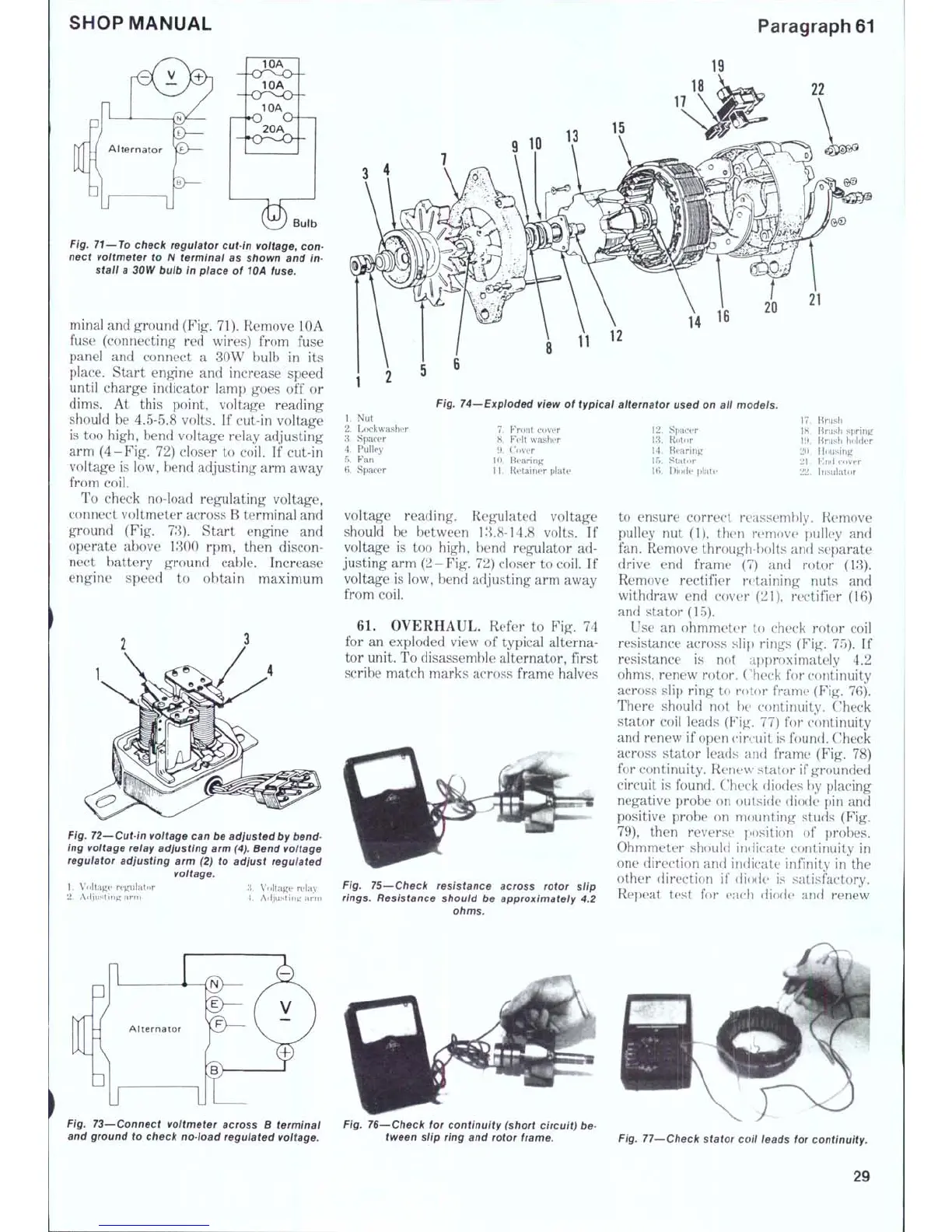
61.
OVERHAUL. Refer to Fig. 74
for an exploded view of typical alterna-
tor unit. To disassemble alternator, first
scribe match marks across frame halves
7.
Front cover
8. Felt washer
9. Cover
10.
Bearing
11.
Retainer plate
12.
Spacer
13.
Rotor
14.
Bearing
15.
Stator
16.
Diode plate
17.
Brush
18.
Brush spring
19.
Brush holder
20.
Housing
21.
Knd cover
22.
Insulator
Fig. 75—Check resistance across rotor siip
rings. Resistance shouid be approximately 4.2
ohms.
to ensure correct reassembly. Remove
pulley nut (1), then remove pulley and
fan. Remove through-bolts and separate
drive end frame (7) and rotor (13).
Remove rectifier retaining nuts and
withdraw end cover (21), rectifier (16)
and stator (15).
Use an ohmmeter to check rotor coil
resistance across slip rings (Fig. 75). If
resistance is not af)proximately 4.2
ohms,
renew rotor. Check for continuity
across slip ring to rotor frame (Fig. 76).
There should not be continuity. Check
stator coil leads (F'i^. 77) for continuity
and renew if open circuit is found. Check
across stator leads and frame (Fig. 78)
for continuity. Renew stator if grounded
circuit is found. Check diodes hy placing
negative probe on outside diode pin and
positive probe on mounting studs (Fig.
79),
then reverse position of probes.
Ohmmeter should indicate continuity in
one direction and indicate infinity in the
other direction if diode is satisfactory.
Repeat test for each diode and renew
Fig. 73—Connect voltmeter across B terminai Fig. 76—Check for continuity (short circuit) be-
and ground to check no-ioad regulated voitage. tween siip ring and rotor frame. Fig. 77—Check stator coii leads for continuity.
29
 Loading...