SHOP MANUAL
Paragraphs 81-82
"28
32
1.
Main shift lever
2.
Retaining ring
3.
Washers
4.
Spring
5.
"0"
ring
6. Shieifi
7. Cover
8. Pins
9.
Shiekl
10.
Interlock ball
11.
Shift rails
12.
Shift forks
13.
Sprinjr
14.
Neutral stop
15.
Detent ball
16.
Spring
17.
"0"
ring
18.
Shift
arm
(pt(»)
19.
Shift rail (range)
20.
Shift fork (range)
21.
Ball
22.
Pin
23.
Shift
;irm
(range)
24.
"0"
ring
25.
Retainer
26.
Shift ever (range)
27.
Set
screw
28.
Shift lever
(pto)
29.
Retainer
30.
Ball
31.
Shift fork
(pto)
32.
Shift rail
33.
Retainer
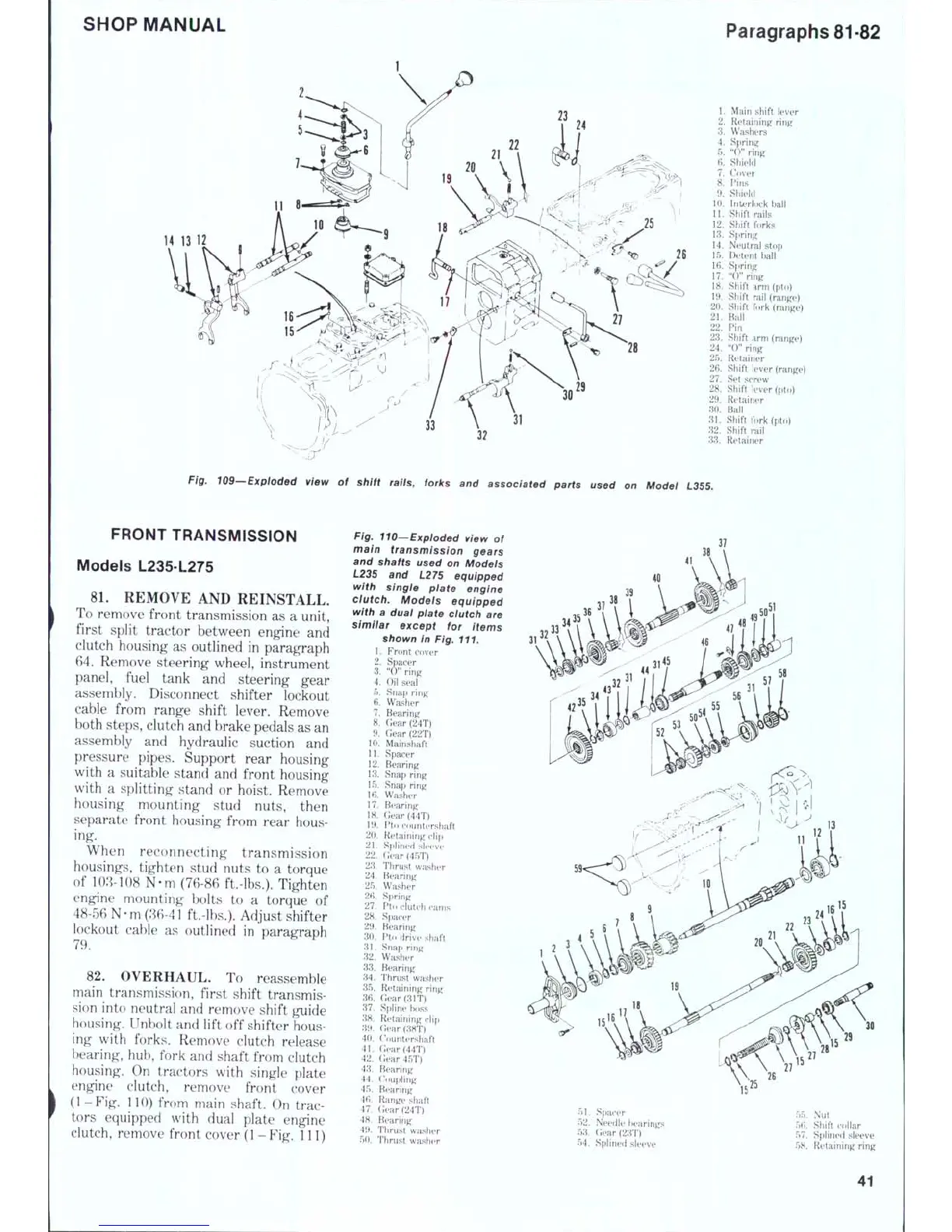
Fig. 109—Exploded view of shift rails, forks and associated parts used on Modei L355.
FRONT TRANSMISSION
Models L235 L275
8L REMOVE
AND
REINSTALL.
To remove front transmission
as a
unit,
first split tractor between engine
and
clutch housing
as
outlined
in
paragraph
64.
Remove steering wheel, instrument
panel, fuel tank
and
steering gear
assembly. Disconnect shifter lockout
cable from range shift lever. Remove
both steps, clutch and brake pedals as an
assembly
and
hydraulic suction
and
pressure pipes. Support rear housing
with
a
suitable stand
and
front housing
with
a
splitting stand
or
hoist. Remove
housing mounting stud nuts, then
separate front housing from rear hous-
ing.
When reconnecting transmission
housings, tighten stud nuts
to a
torque
of 103-108
N-m
(76-86 ft.-lbs.). Tighten
engine mounting bolts
to a
torque
of
48-56 N-m
(36-41
ft.-lbs.). Adjust shifter
lockout cable
as
outlined
in
paragraph
82.
OVERHAUL.
To
reassemble
main transmission, first shift transmis-
sion into neutral
and
remove shift guide
housing. Unbolt and lift
off
shifter hous-
ing with forks. Remove clutch release
bearing, hub, fork
and
shaft from clutch
housing.
On
tractors with single plate
engine clutch, remove front cover
(1
-Fig. 110) from main shaft.
On
trac-
tors equipped with dual plate engine
clutch, remove front cover
(1
-
Fig.
Ill )
Fig. 110—Expioded view of
main transmission gears
and shafts used on Models
L235 and L275 equipped
with singie piate engine
dutch. Models equipped
with a dual plate dutch are
simiiar except for items
shown in Fig. 111.
1.
Front cover
2.
Spacer
3.
"0"
ring
4.
Oil
seal
5.
Snap ring
6. Washer
7.
Bearing
8. Gear(24T)
9.
Gear(22T)
10.
Mainshaft
11.
Spacer
12.
Bearing
13.
Snap ring
15.
Snap ring
16.
Washer
17.
Bearing
lH.
(;ear(44T)
19.
Pto
countershaft
20.
Retaining clifi
21.
Spiined sieeve
22.
Gear(45T)
23.
Thrust washer
24.
Bearing
25.
Washer
26.
Spring
27.
Pto
clutch cams
28.
Spacer
29.
Bearing
30.
Pto
drive sfiaft
31.
Snap ring
32.
Washer
33.
Bearing
34.
Thrust washer
35.
Retaining ring
36.
(;ear(31T)
37.
Spline boss
38.
Retaining clip
39 ( ; ( 3 8 T
()
40.
Countershaft
41.
Gear(44T)
42.
Gfar45T)
43.
Bearing
44.
('oupling
45.
Bearing
46.
Range shaft
47.
Clear
(24T)
48.
Bearing
49.
Thrust wa.sher
50.
Thrust washer
51.
Spacer
52.
NeeiJIe hearings
53.
Gear(2;rD
54.
Spiined sleeve
55.
Nut
56,
Shift collar
57,
Spiined sleeve
58.
Retaining ring
41
 Loading...