Paragraph 107
\
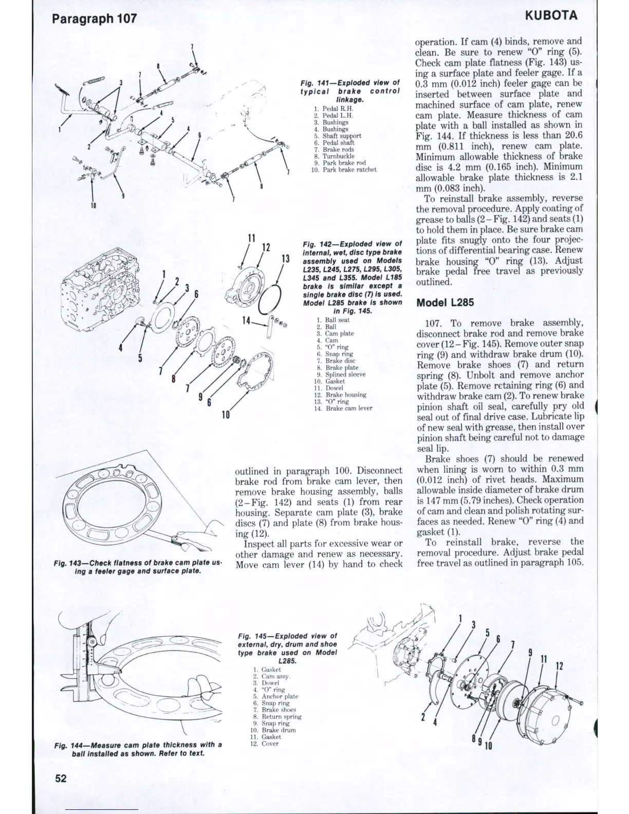
Fig. 141—Exploded view of
typical brake control
linkage.
1.
Pedal R.H.
2.
Pedal L.H.
3.
Bushings
4.
Bushings
5.
Shaft support
6. Pedal shaft
7. Brake rods
8. Turnhuckle
9. Park hrake rod
10.
Park hrake ratchet
Fig. 142—Exploded view of
Internal, wet, disc type brake
assembly used on Models
L235, L245, L275, L295, L305,
L345 and L355. Model LIBS
brake is similar except a
single brake disc (7) is
used.
Model L2B5 brake is shown
in Fig. 145.
1.
Ball seat
2.
Ball
3.
Cam plate
4.
Cam
5.
"0" ring
6. Snap ring
7.
Brake disc
8. Brake plate ; .
9. Spiined sleeve
10.
Gasket
11.
Dowel
12.
Brake housing
13.
"0" ring
14.
Brake cam lever
g.
143—Check flatness of brake cam plate us-
ing a feeler gage and surface plate.
outlined in paragraph 100. Disconnect
brake rod from brake cam lever, then
remove brake housing assembly, balls
(2-Fig. 142) and seats (1) from rear
housing. Separate cam plate (3), brake
discs (7) and plate (8) from brake hous-
ing (12).
Inspect all parts for excessive wear or
other damage and renew as necessary.
Move cam lever (14) by hand to check
KUBOTA
operation. If cam (4) binds, remove and
clean. Be sure to renew "0" ring (5).
Check cam plate flatness (Fig. 143) us-
ing a surface plate and feeler gage. If a
0.3 mm (0.012 inch) feeler gage can be
inserted between surface plate and
machined surface of cam plate, renew
cam plate. Measure thickness of cam
plate with a ball installed as shown in
Fig. 144. If thickness is less than 20.6
mm (0.811 inch), renew cam plate.
Minimum allowable thickness of brake
disc is 4.2 mm (0.165 inch). Minimum
allowable brake plate thickness is 2.1
mm (0.083 inch).
To reinstall brake assembly, reverse
the removal procedure. Apply coating of
grease to balls
(2
-
Fig.
142) and seats (1)
to hold them in place. Be sure brake cam
plate fits snugly onto the four projec-
tions of differential bearing case. Renew
brake housing "0" ring (13). Adjust
brake pedal free travel as previously
outlined.
Model L285
107.
To remove brake assembly,
disconnect brake rod and remove brake
cover (12-Fig. 145). Remove outer snap
ring (9) and withdraw brake drum (10).
Remove brake shoes (7) and return
spring (8). Unbolt and remove anchor
plate (5). Remove retaining ring (6) and
withdraw brake cam
(2).
To renew brake
pinion shaft oil seal, carefully pry old
seal out of final drive case. Lubricate lip
of new seal with grease, then install over
pinion shaft being careful not to damage
seal lip.
Brake shoes (7) should be renewed
when lining is worn to within 0.3 mm
(0.012 inch) of rivet heads. Maximum
allowable inside diameter of brake drum
is 147 mm (5.79 inches). Check operation
of cam and clean and polish rotating sur-
faces as needed. Renew "0" ring (4) and
gasket (1).
To reinstall brake, reverse the
removal procedure. Adjust brake pedal
free travel as outlined in paragraph 105.
Fig. 144-
ball
-Measure cam plate thickness with a
instalied as shown. Refer to text
Fig. 145—Exploded view of
externai, dry, drum and shoe
type brake used on Modei
L2B5.
1.
Gasket
2.
Cam assy.
3.
Dowel
4.
"O" ring
5.
Anchor plate
6. Snap ring
7.
Brake shoes
8. Return spring
9. Snap ring
10.
Brake drum
11.
Gasket
12.
Cover
12
52
 Loading...