2-14
KC157
2. Press in and turn the bulb counterclockwise to
remove. Press in and turn clockwise to install the
bulb.
3. Insert the bulb socket assembly into the housing
and turn it clockwise to secure.
RUNNING LIGHTS/BACK-UP
LIGHTS
The running lights are located outboard of the head-
lights, and the back-up lights are outboard of the tail-
lights/brakelights. To replace the bulbs, use the
following procedure.
1. Rotate the bulb socket counterclockwise to release
from light housing; then press in on the bulb and
turn counterclockwise to release from the socket.
KC158A
2. Install a new bulb and press in rotating clockwise
to secure; then place the socket into the light hous-
ing and turn clockwise to secure.
KC158B
CHECKING/ADJUSTING
HEADLIGHT AIM
The headlights can be adjusted vertically and horizon-
tally. The geometric center of the HIGH beam light
zone is to be used for vertical and horizontal aiming.
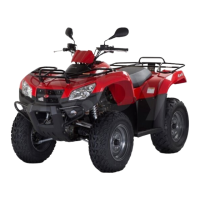
1. Position the ATV on a level floor so the headlights
are approximately 6.1 m (20 ft) from an aiming
surface (wall or similar aiming surface).
ATV-0070C
NOTE: There should be an average operating
load on the ATV when adjusting the headlight aim.
2. Measure the distance from the floor to the
mid-point of each headlight.
3. Using the measurements obtained in step 2, make
horizontal marks on the aiming surface.
4. Make vertical marks which intersect the horizontal
marks on the aiming surface directly in front of the
headlights.
5. Switch on the lights. Make sure the HIGH beam is
on. DO NOT USE LOW BEAM.
6. Observe each headlight beam aim. Proper aim is
when the most intense beam is centered on the ver-
tical mark 5 cm (2 in.) below the horizontal mark
on the aiming surface.
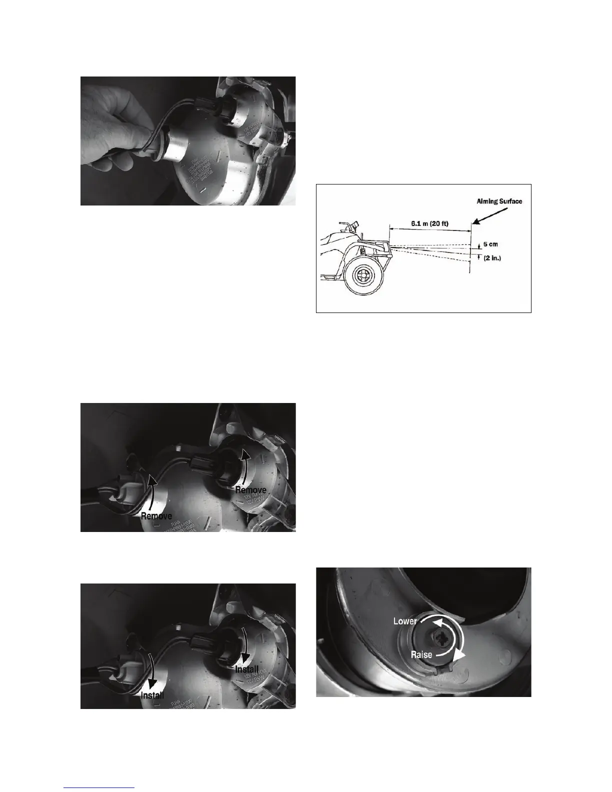
7. Adjust each headlight by turning the adjuster knob
counterclockwise to raise the beam or clockwise to
lower the beam.
KC0108A
 Loading...