Table
of
Contents
Removing
Engine/Transmission
..............................
3-7
Top-Side
Components.............................................
3-9
Removing
Top- Side
Components
...........................
3-9
Servicing
Top-Sid e
Components...........................
3-13
Installing
Top-S ide
Components
...........................
3-21
Left-Side
Components
..........................................
3-25
Removing
Left-Side
Components
.........................
3-26
Installing
Left-Side
Components
...........................
3-28
Right-Side
Components
........................................
3-29
Removing
Right-Side
Components
.......................
3-29
Servicing
Right-Side
Components
........................
3-33
Installing
Right-Side
Components.........................
3-33
Center
Crankcase
Components............................
3-36
Separating
Crankcase
Halves...............................
3-37
Disassembling
Crankcase
Half
.............................
3-37
Servicing
Center
Crankcase
Components
............
3-39
Assembling
Crankcase
Half
..................................
3-42
Joining
Crankcase
Halves.....................................
3-44
Installing
Engine/Transmission
..............................
3-44
Removing
Engine/
Transmission
Many
s
e
rv
ice
procedures
ca
n
be
p
e
rformed
w
i
thou
t
removing
the
engine/transmission
from
the
frame.
Closely
obs
e
rve
the
note
introducing
each
sub-section
for
thi
s
important
information.
AT
TH
I
S
P
O
IN
T
If
the
technician’s
objective
is
to
service
Top-Side
Components,
Left-Side
Components,
or
Right-Side
Components,
the
engine/transmission
does
not
have
to
be
removed
from
the
frame
.
AT
TH
I
S
P
O
IN
T
If
the
technician’s
objective
is
to
service/replace
left-side
cover
oil
seals
or
the
oil
strainer
(from
beneath the
engine/transm
i
ssion)
,
the
eng
i
ne/transmission
does
not
have
to
be
removed
from
the frame
.
Secure
the
ATV
on
a
support
stand
to
el
eva
te
the wheels.
2.
Remove
the
heat
shield;
then
remove
the
gas
tank
(see
Section
4).
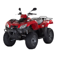
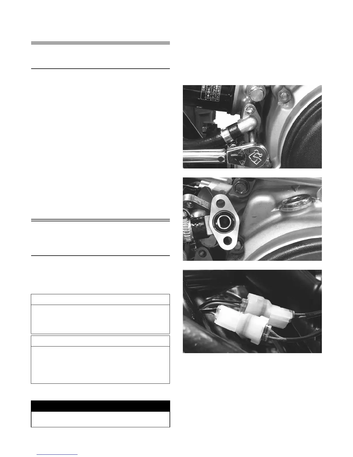
3.
Remove
the
oil
fittings
from
the
engine
and account
for
two
O-rings;
then
disconnect
the
oil
te
mperatur
e
conn
ec
tor
a
nd
cooling
fan
c
onn
ec
tor.
KC251
KC250
KC249
4.
Disconne
ct
the
spe
e
dome
ter
sensor;
then
remove
the
E-clip
securing
the
shift
rod
to
the
shift
a
rm and
disconnect
the
shift
rod.
Account
for
a
bushing
and
flat
washer.
WARNING
Make
sure
the
ATV
is
solidly
supported
on
the
sup- port
stand
to
avo
i
d
inju
ry
.
1.
Remove
the
front
rack,
left
and
right
footwells, and
fron
t
body
p
a
n
el
(se
e
Section
8);
then
dis
c
onnect
the
negative
battery
cable
from
the
battery.
3-7
 Loading...