EasyManuals Logo
Home>Lamtec>Control Systems>AEC-TPS

Lamtec AEC-TPS User Manual

Lamtec AEC-TPS
284 pages
To Next Page IconTo Next Page
To Previous Page IconTo Previous Page
Page #78 background imageLoading...
Page #78 background image
77
4 CMS Components
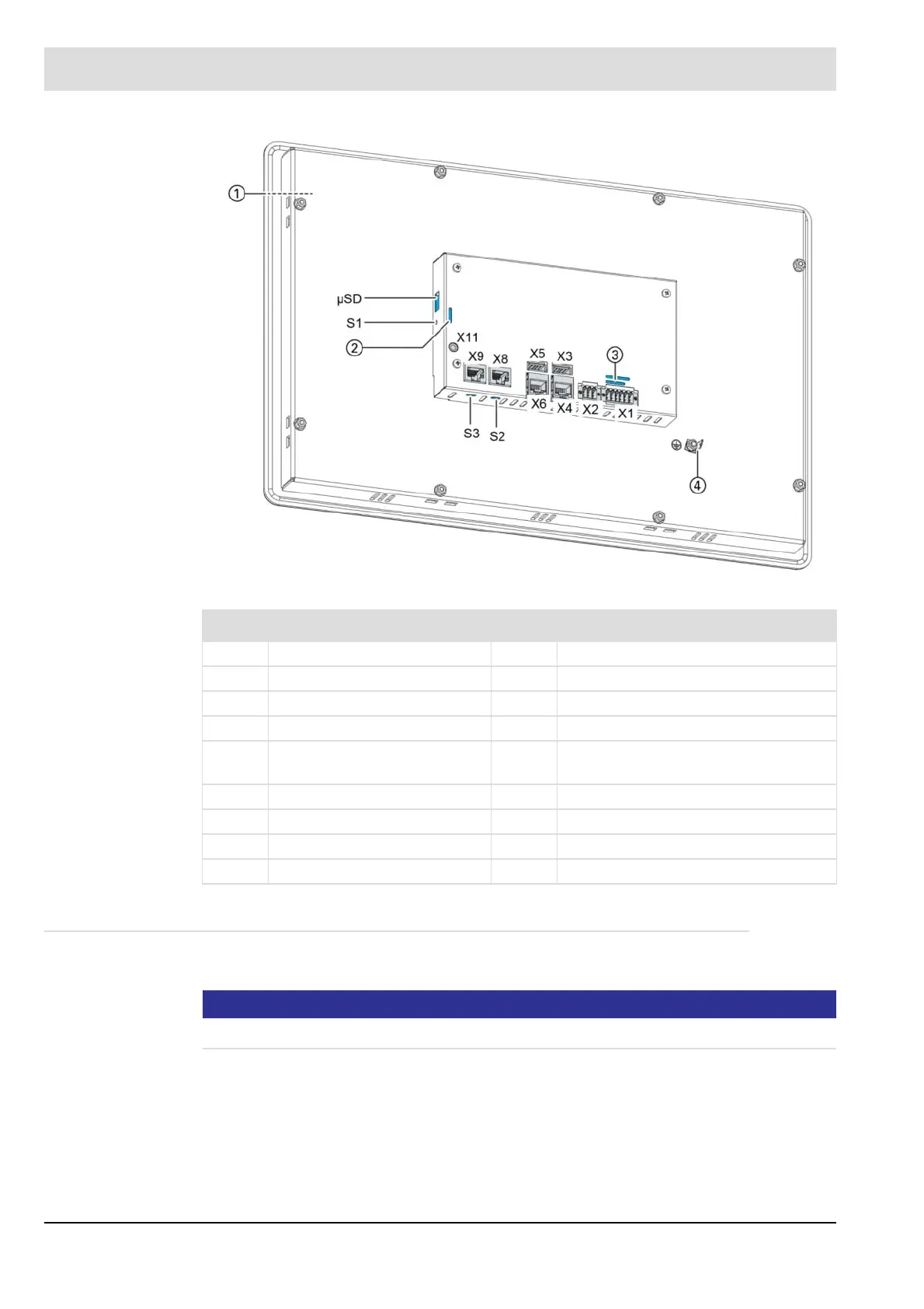
Fig. 4-45 GUI615 connection diagram
4.8.5 Interfaces
2x Ethernet, 10/100 Base, RJ45 (1 active)
NOTICE
Consult the Ethernet specification.
No. Description No. Description
1 Display 16,5 " X6 EtherCAT
2 LEDs: PWR, Run/Stop, Error X8 CAN-Bus
3 LEDs: Power, digital I/O X9 RS-232/RS-485
4 Ground X11 Do not use
X1 Power supply, digital inputs
and outputs
S1 Do not use
X2 Analogue inputs S2 Termination resistor CAN (120 )
X3 USB 2.0 S3 Terminating resistor RS-485 (120 )
X4 Ethernet
X5 USB 2.0

Table of Contents

Questions and Answers:

Question and Answer IconNeed help?

Do you have a question about the Lamtec AEC-TPS and is the answer not in the manual?

Lamtec AEC-TPS Specifications

General IconGeneral
BrandLamtec
ModelAEC-TPS
CategoryControl Systems
LanguageEnglish

Related product manuals