66
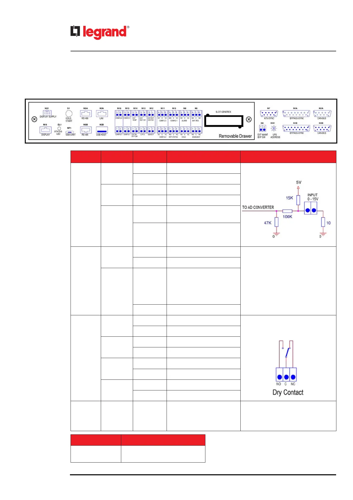
4.5 SSS interface
TERMINAL PINS FUNCTION
Analogic
floating
inputs
N16
1-2 CONFIGURABLE CONTACT 3 Maximum input voltage: 15V
15 kΩ pull-up
3-4 CONFIGURABLE CONTACT 4
N15
1-2 CONFIGURABLE CONTACT 1
3-4 CONFIGURABLE CONTACT 2
N14
1-2
EXTERNAL MAINTENANCE
BYPASS SWITCH
3-4
EXTERNAL TEMPERATURE
Maximum Input Voltage: 5V
(not available at the moment)
Digital
floating
inputs
N13
1-2 EPO
Maximum input voltage: 5V
1 kΩ pull-up
3-4 EXTERNAL OUTPUT SWITCH
N12
1-2
GENSET
It allows the UPS to know if
there is an external generator.
If the contact is closed, the
generator is present.
3-4 EXTERNAL BATTERY SWITCH
Output
contacts
N11
4-5-6 CONFIGURABLE CONTACT 3 NC/NO contacts
30 Vdc -1 A
125 Vac - 0,5 A (resistive load).
1-2-3 CONFIGURABLE CONTACT 2
N10
4-5-6 CONFIGURABLE CONTACT 1
1-2-3 BYPASS STATUS
N9
4-5-6 ALARM
1-2-3 OVERLOAD
N8
4-5-6 BATTERY AUTONOMY RESERVE
1-2-3 MAINS/BATTERY STATUS
N6 1-2
AUXILIARY REMOTE BYPASS
CONTAC T
It is possible to enable the forced
bypass mode through this NO contact
CONNECTOR TERMINAL
N3B
USB HOST
Port used for FW updates
4. Installation
 Loading...