GR30/GM30/GR50, Pin Assignments and Sockets
83
Appendix B Pin Assignments and Sockets
B.1 GR30/GM30
Description Some applications require knowledge of the pin assignments for the GR30/GM30
ports. In this chapter, the pin assignments and sockets for the ports of the
GR30/GM30 are explained.
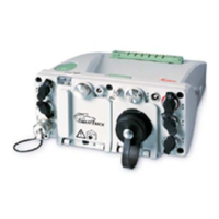
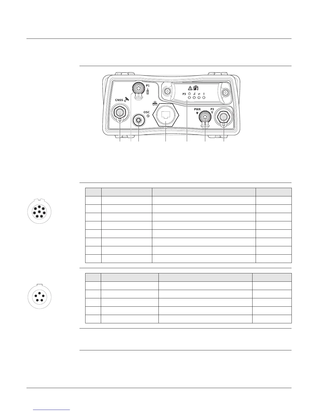
Ports on the
instrument rear
panel
Pin assignments for
P1: Serial Port
Pin assignments for
PWR: Power port
Sockets
a) GNSS:GNSS antenna port TNC
b) P1: Serial port, 8 pin LEMO
c) OSC: Oscillator port
d) Ethernet port: Ruggedised RJ45
e) P3: Communication slot-in port
f) PWR: Power port, 5 pin LEMO, dual input
g) P3: Communication slot-in port antenna,
TNC
GR10_015
ac d e f gb
1
7
6
8
5
4
3
2
PIN_003
Pin Signal Name Function Direction
1 RTS RS232, ready to send Out
2 CTS RS232, clear to send In
3 GND Signal ground -
4 RxD RS232, receive data In
5 TxD RS232, transmit data Out
6 ID Indentification pin In or out
7 GPIO RS232, configurable function In or out
8 +12 V12 V power supply out Out
1
5
43
2
PIN_004
Pin Signal Name Function Direction
1 PWR1 Power input, 10.5 V-28 VIn
2 ID1 Identification pin In
3 GND Signal ground -
4 PWR2 Power input, 10.5 V-28 VIn
5 ID2 Identification pin In
Port P1: LEMO-1, 8 pin, LEMO HMA.1B.308.CLN
Port PWR: LEMO-1, 5 pin, LEMO HMG.1B.305.CLNP
 Loading...