Page 10
Unit Placement
See Unit Dimensions on page 5 for sizing mounting slab,
platforms or supports.
CAUTION
In order to avoid injury, take proper precaution when
lifting heavy objects..
POSITIONING CONSIDERATIONS
Consider the following when positioning the unit:
• Some localities are adopting sound ordinances based
on the unit's sound level registered from the adjacent
property, not from the installation property. Install the
unit as far as possible from the property line.
• When possible, do not install the unit directly outside
a window. Glass has a very high level of sound trans-
mission. For proper placement of unit in relation to a
window see the provided illustration in gure 6, detail A.
PLACING UNIT ON SLAB
When installing unit at grade level, the top of the slab
should be high enough above grade so that water from
higher ground will not collect around the unit. The slab
should have a slope tolerance as described in gure 6,
detail B.
NOTE – If necessary for stability, anchor unit to slab as
described in gure 6, detail D.
ELEVATING THE UNIT
Units are outtted with elongated support feet as illustrat-
ed in gure 6, detail C.
If additional elevation is necessary, raise the unit by ex-
tending the height of the unit support feet. Use a 2-inch
(50.8mm) Schedule 40 female threaded adapter to raise
the height of the unit.
The specied coupling will t snugly into the recessed por-
tion of the feet. Use additional 2-inch (50.8mm) Schedule
40 male threaded adaptors which can be threaded into the
female threaded adaptors to make additional adjustments
to the level of the unit.
NOTE – Keep the height of extenders short enough to
ensure a sturdy installation. If it is necessary to extend
the height further than what is stable, consider a dierent
type of eld-fabricated framework that is sturdy enough for
greater heights.
Installation
See
NOTES
See NOTES
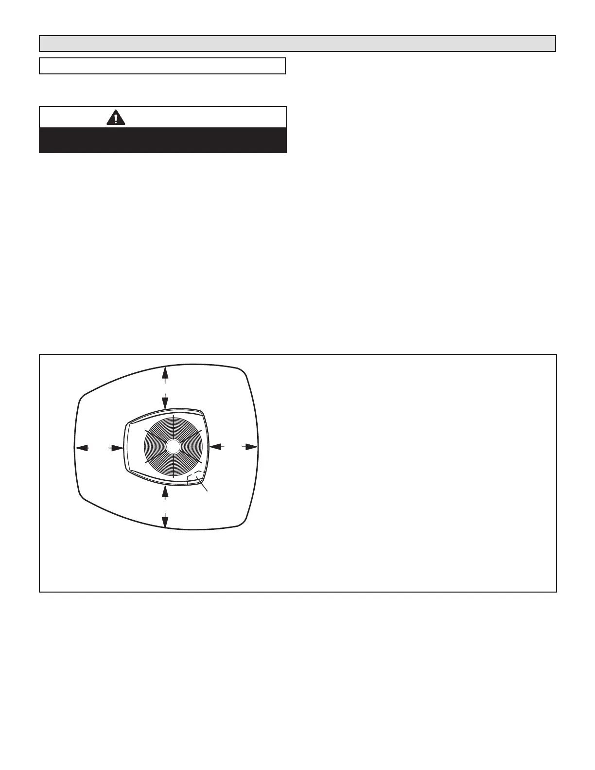
NOTES:
Service clearance of 30 in. must be maintained on one of the sides
adjacent to the control box.
Clearance to one of the other three sides must be 36 in.
Clearance to one of the remaining two sides may be 12 in. and the
final side may be 6 in.
A clearance of 24 in. must be maintained between two units.
48 in. clearance required on top of unit.
See
NOTES
See NOTES
Control
Box
NOTICE: Specific applications may require adjustment of the listed installation clearances to provide protection for
the unit from physical damage or to avoid conditions which limit operating efficiency. (Example: Clearances may
have to be increased to prevent snow or ice from falling on the top of the unit. Additional clearances may also be
required to prevent air recirculation when the unit is installed under a deck or in another tight space.)
FIGURE 5. Installation Clearances

 Loading...

