Page 34
Table 6 continued
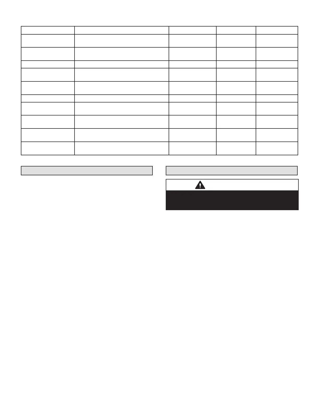
Designator Description Input Output Common
Suction Pressure Out
Pressure transducer Supply Voltage Pin 1
of 3
5 VDC
Suction Pressure In
Pressure transducer output voltage Pin 2
of 3
0-4.5 VDC
Suction Pressure GND Pressure transducer GND Pin 3 of 3 VDC Com
Liquid Pressure Out
Pressure transducer Supply Voltage Pin 1
of 3
5 VDC
Liquid Pressure In
Pressure transducer Supply Voltage Pin 2
of 3
0-4.5 VDC
Liquid Pressure GND Pressure transducer GND Pin 3 of 3 VDC Com
SUCT1
Suction Line Temperature Sensor Supply -
Pin 1 of 4
0-4.5 VDC
SUCT2
Suction Line Temperature Sensor Supply -
Pin 2 of 4
LIQ1
Liquid Line Temperature Sensor Supply -
Pin 3 of 4
0-4.5 VDC
LIQ2
Liquid Line Temperature Sensor Supply -
Pin 4 of 4
Servicing Units Delivered Void of Charge
If the outdoor unit is void of refrigerant, clean the system
using the procedure described below.
1 - Leak test the system using the procedure outlined
on page 23.
2 - Evacuate the system using procedure outlined on
page 24.
3 - Use nitrogen to break the vacuum and install a new
lter drier in the system.
4 - Evacuate the system again using procedure
outlined on page 24.
5 - Weigh in refrigerant using procedure outlined in
gure 48.
6 - Monitor the system to determine the amount of
moisture remaining in the oil. It may be necessary
to replace the lter drier several times to achieve the
required dryness level. If system dryness is not
veried, the compressor will fail in the future.
Unit Start-Up
IMPORTANT
If unit is equipped with a crankcase heater, it should
be energized 24 hours before unit start-up to prevent
compressor damage as a result of slugging.
1 - Rotate fan to check for binding.
2 - Inspect all factory- and eld-installed wiring for
loose connections.
3 - After evacuation is complete, open both the liquid and
vapor line service valves to release the refrigerant
charge contained in outdoor unit into the system.
4 - Replace the stem caps and tighten to the value
listed in table 1.
5 - Check voltage supply at the disconnect switch. The
voltage must be within the range listed on the unit's
nameplate. If not, do not start the equipment until
you have consulted with the power company and
the voltage condition has been corrected.
6 - Set the thermostat for a cooling demand. Turn on
power to the indoor unit and close the outdoor unit
disconnect switch to start the unit.
7 - Recheck voltage while the unit is running. Power
must be within range shown on the nameplate.
8 - Check system for sucient refrigerant by using the
procedures listed in the System Refrigerant section
on page 76.

 Loading...

