Page 13
5 - If necessary, run the condensate line into a condensate
pump to meet drain line slope requirements. The
pump must be rated for use with condensing
furnaces. Protect the condensate discharge line
IURPWKHSXPSWRWKHRXWVLGHWRDYRLGIUHH]LQJ
6 - Continue with exhaust, condensate and intake piping
installation according to instructions.
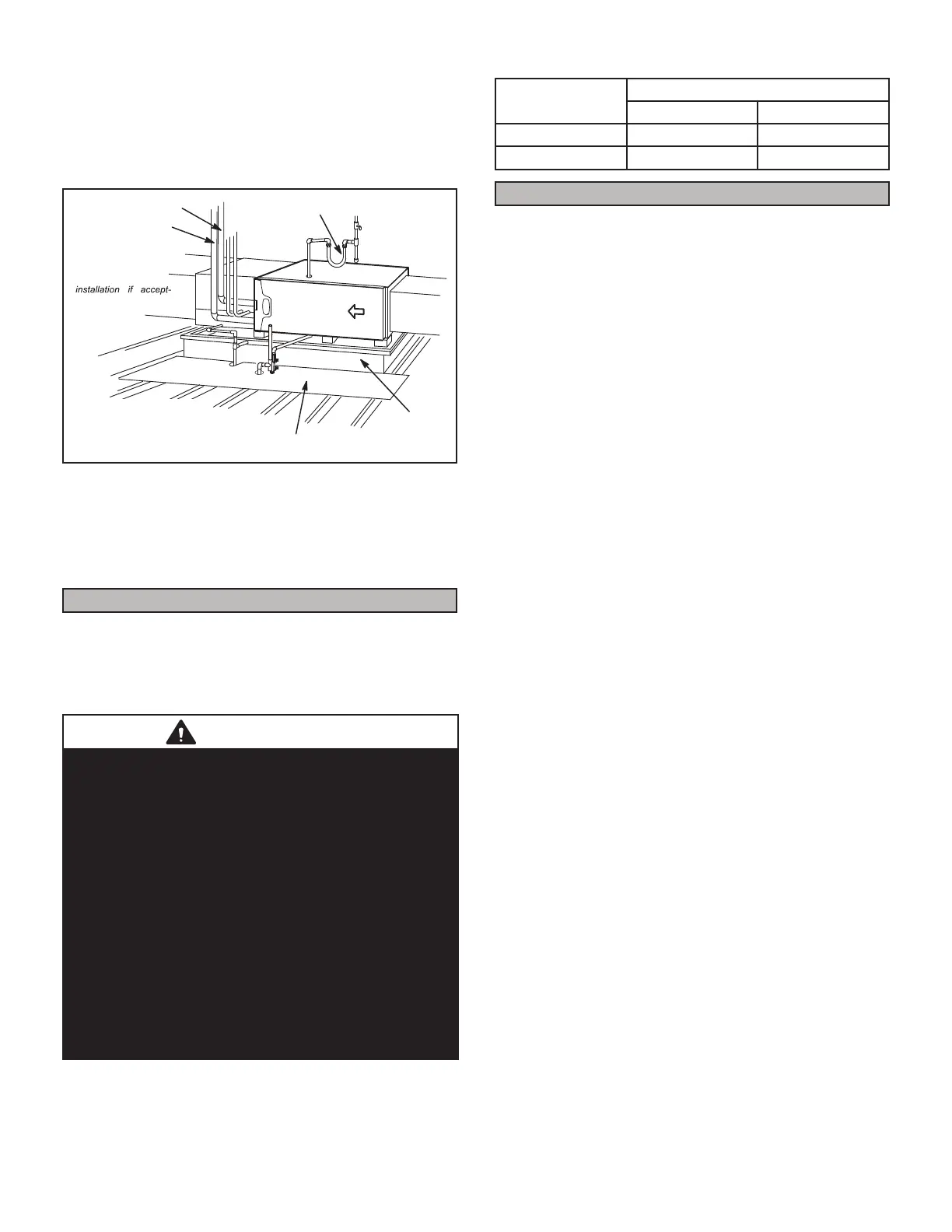
*Gas connector may be
used for Canadian
able by local authority
having jurisdiction.
*GAS CONNECTION
RAISED
PLATFORM
SERVICE PLATFORM
INTAKE PIPE
EXHAUST PIPE
Figure 19
Return Air -- Horizontal Applications
Return air may be brought in only through the end of a
IXUQDFHLQVWDOOHGLQWKHKRUL]RQWDOSRVLWLRQ7KHIXUQDFHLV
equipped with a removable bottom panel to faciliate instal-
lation. See Figure 15.
Filters
7KLVXQLWLVQRWHTXLSSHGZLWKD¿OWHURUUDFN$¿HOGSUR-
YLGHG KLJK YHORFLW\ UDWHG ¿OWHU LV UHTXLUHG IRU WKH XQLW WR
RSHUDWHSURSHUO\7$%/(OLVWVUHFRPPHQGHG¿OWHUVL]HV
$¿OWHUPXVWEHLQSODFHZKHQHYHUWKHXQLWLVRSHUDWLQJ
.
WARNING
,IDKLJKHႈFLHQF\¿OWHULVEHLQJLQVWDOOHGDVSDUWRIWKLV
V\VWHPWRHQVXUHEHWWHULQGRRUDLUTXDOLW\WKH¿OWHUPXVW
EH SURSHUO\ VL]HG +LJKHႈFLHQF\ ¿OWHUV KDYH D KLJKHU
VWDWLFSUHVVXUHGURSWKDQVWDQGDUGHႈFLHQF\JODVVIRDP
¿OWHUV,IWKHSUHVVXUHGURSLVWRRJUHDWV\VWHPFDSDFLW\
and performance may be reduced. The pressure drop
may also cause the limit to trip more frequently during
WKHZLQWHUDQGWKHLQGRRUFRLOWRIUHH]HLQWKHVXPPHU
resulting in an increase in the number of service calls.
%HIRUH XVLQJ DQ\ ¿OWHU ZLWK WKLV V\VWHP FKHFN WKH
VSHFL¿FDWLRQVSURYLGHGE\WKH¿OWHUPDQXIDFWXUHUDJDLQVW
the data given in the appropriate Lennox Product
6SHFL¿FDWLRQVEXOOHWLQ$GGLWLRQDOLQIRUPDWLRQLVSURYLGHG
in Service and Application Note ACC002
(August 2000).
TABLE 1
Furnace
Cabinet Width
)LOWHU6L]H
Side Return Bottom Return
17-1/2” 16 X 25 X 1 (1) 16 X 25 X 1 (1)
21” 16 X 25 X 1 (1) 20 X 25 X 1 (1)
Duct System
8VH LQGXVWU\DSSURYHG VWDQGDUGV WR VL]H DQG LQVWDOO WKH
supply and return air duct system. Figure 20 shows the
correct supply and return duct installation. Refer to ACCA
Manual D. This will result in a quiet and low-static system
that has uniform air distribution.
NOTE - 7KLVIXUQDFHLVQRWFHUWL¿HGIRURSHUDWLRQLQKHDW-
LQJ PRGH LQGRRU EORZHU RSHUDWLQJ DW VHOHFWHG KHDWLQJ
VSHHGZLWKDQH[WHUQDOVWDWLFSUHVVXUHZKLFKH[FHHGV
LQFKHV ZF 2SHUDWLRQ DW WKHVH FRQGLWLRQV PD\ UHVXOW LQ
LPSURSHUOLPLWRSHUDWLRQ
Supply Air Plenum
If the furnace is installed without a cooling coil, a remov-
able access panel should be installed in the supply air
duct. The access panel should be large enough to per-
mit inspection of the heat exchanger. The furnace access
panel must always be in place when the furnace is oper-
DWLQJDQGLWPXVWQRWDOORZOHDNV)RUKRUL]RQWDOXQLWVLQ-
stall self tapping screws in the three evaporator coil screw
KROHVPDGHIRUKRUL]RQWDODSSOLFDWLRQVWRVHDOWKHWRSFDS
to the vestibule panel.
Return Air Plenum
NOTE - Return air must not be drawn from a room
where this furnace, or any other gas-fueled appliance
(i.e., water heater), or carbon monoxide-producing de-
YLFHLHZRRG¿UHSODFHLVLQVWDOOHG
When return air is drawn from a room, a negative pressure
is created in the room. If a gas appliance is operating in
DURRPZLWKQHJDWLYHSUHVVXUHWKHÀXHSURGXFWVFDQEH
pulled back down the vent pipe and into the room. This
UHYHUVHÀRZRIWKHÀXHJDVPD\UHVXOWLQLQFRPSOHWHFRP-
bustion and the formation of carbon monoxide gas. This
raw gas or toxic fumes might then be distributed through-
out the house by the furnace duct system.
Return air can be brought in through the bottom or either
side of the furnace (return air brought into either side of
IXUQDFHDOORZHGLQXSÀRZDSSOLFDWLRQVRQO\,IDIXUQDFH
with bottom return air is installed on a platform, make an
airtight seal between the bottom of the furnace and the
platform to ensure that the unit operates properly and
VDIHO\8VH¿EHUJODVVVHDOLQJVWULSVFDXONLQJRUHTXLYD-
lent sealing method between the plenum and the furnace
FDELQHWWRHQVXUHDWLJKWVHDO,ID¿OWHULVLQVWDOOHGVL]HWKH
UHWXUQDLUGXFWWR¿WWKH¿OWHUIUDPH
 Loading...