Page 16
Joint Cementing Procedure
All cementing of joints should be done according to the
VSHFL¿FDWLRQVRXWOLQHGLQ$670'
DANGER
DANGER OF EXPLOSION!
Fumes from PVC glue may ignite during system check.
Allow fumes to dissipate for at least 5 minutes before
placing unit into operation..
1 - Measure and cut vent pipe to desired length.
2 - Debur and chamfer end of pipe, removing any ridges
or rough edges. If end is not chamfered, edge of pipe
PD\UHPRYHFHPHQWIURP¿WWLQJVRFNHWDQGUHVXOWLQ
a leaking joint.
NOTE - &KHFNWKHLQVLGHRIYHQWSLSHWKRURXJKO\IRU
DQ\REVWUXFWLRQWKDWPD\DOWHUIXUQDFHRSHUDWLRQ
3 - Clean and dry surfaces to be joined.
7HVW ¿W MRLQW DQG PDUN GHSWK RI ¿WWLQJ RQ RXWVLGH RI
pipe.
5 - Uniformly apply a liberal coat of PVC primer for PVC
or use a clean dry cloth for ABS to clean inside socket
VXUIDFH RI ¿WWLQJ DQG PDOH HQG RI SLSH WR GHSWK RI
¿WWLQJVRFNHW
NOTE - 7LPHLV FULWLFDO DW WKLVVWDJH 'R QRW DOORZ
SULPHUWRGU\EHIRUHDSSO\LQJFHPHQW
6 - Promptly apply solvent cement to end of pipe and
LQVLGH VRFNHW VXUIDFH RI ¿WWLQJ &HPHQW VKRXOG EH
applied lightly but uniformly to inside of socket. Take
care to keep excess cement out of socket. Apply
second coat to end of pipe.
7 - Immediately after applying last coat of cement to
pipe, and while both inside socket surface and end
of pipe are wet with cement, forcefully insert end of
pipe into socket until it bottoms out. Turn PVC pipe
1/4 turn during assembly (but not after pipe is fully
inserted) to distribute cement evenly. DO NOT turn
ABS or cellular core pipe.
NOTE - $VVHPEO\ VKRXOG EH FRPSOHWHG ZLWKLQ
VHFRQGV DIWHU ODVW DSSOLFDWLRQ RI FHPHQW +DPPHU
EORZVVKRXOGQRWEHXVHGZKHQLQVHUWLQJSLSH
8 - After assembly, wipe excess cement from pipe at
HQGRI¿WWLQJVRFNHW$SURSHUO\PDGHMRLQWZLOOVKRZ
a bead around its entire perimeter. Any gaps may
LQGLFDWH DQ LPSURSHU DVVHPEO\ GXH WR LQVXႈFLHQW
solvent.
9 - Handle joints carefully until completely set.
Venting Practices
* See Piping and Fittings Specifications table
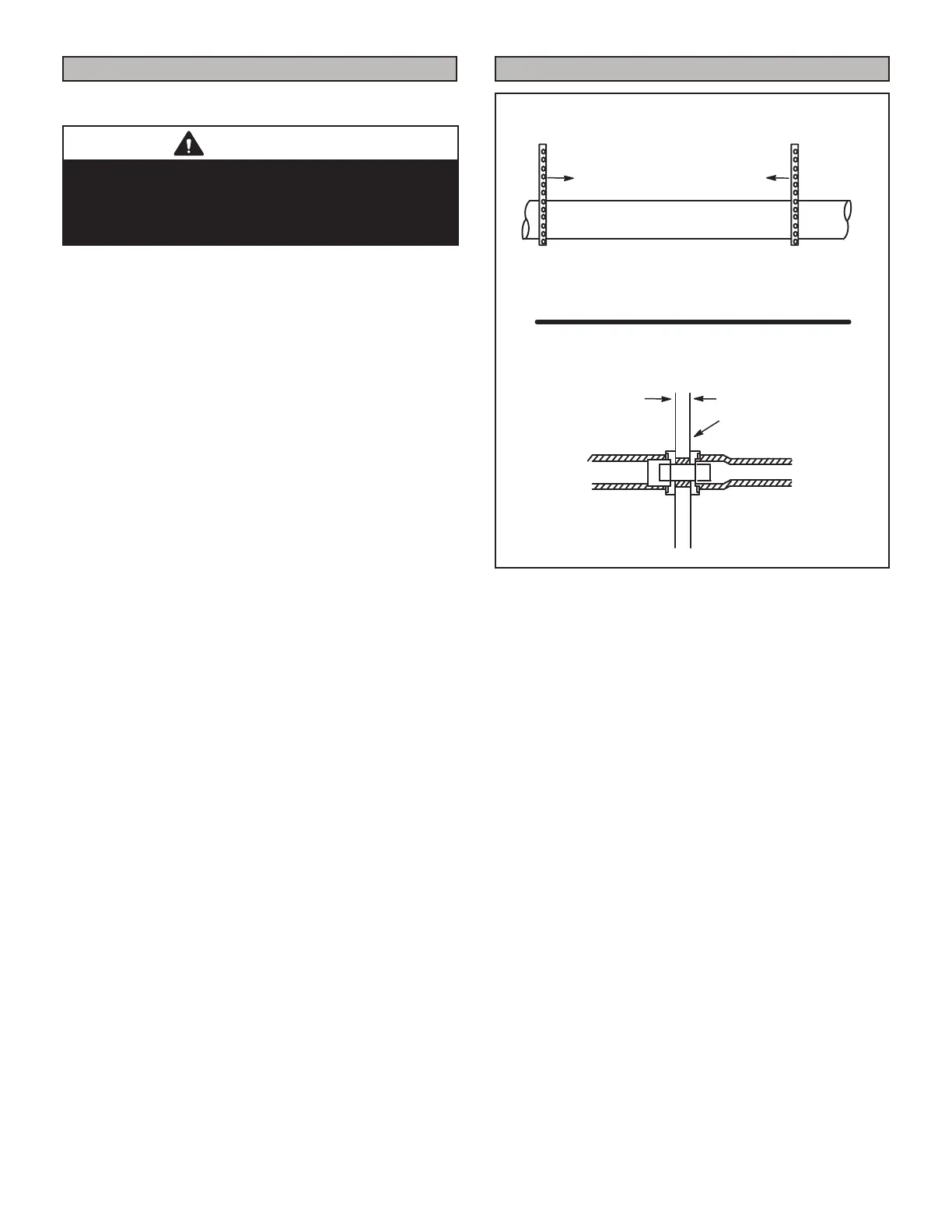
Piping Suspension Guidelines
NOTE - Isolate piping at the point where it exits the outside wall or
roof in order to prevent transmission of vibration to the structure.
SCHEDULE 40
PVC - 5'
all other pipe* - 3'
Wall
edistuoedisni
24” maximum
3/4” minimum
Wall Thickness Guidelines
Figure 21
1 - In areas where piping penetrates joists or interior
walls, hole must be large enough to allow clearance
on all sides of pipe through center of hole using a
hanger.
2 - When furnace is installed in a residence where unit
is shut down for an extended period of time, such
as a vacation home, make provisions for draining
condensate collection trap and lines.
 Loading...