Page 44
Unit Start-Up
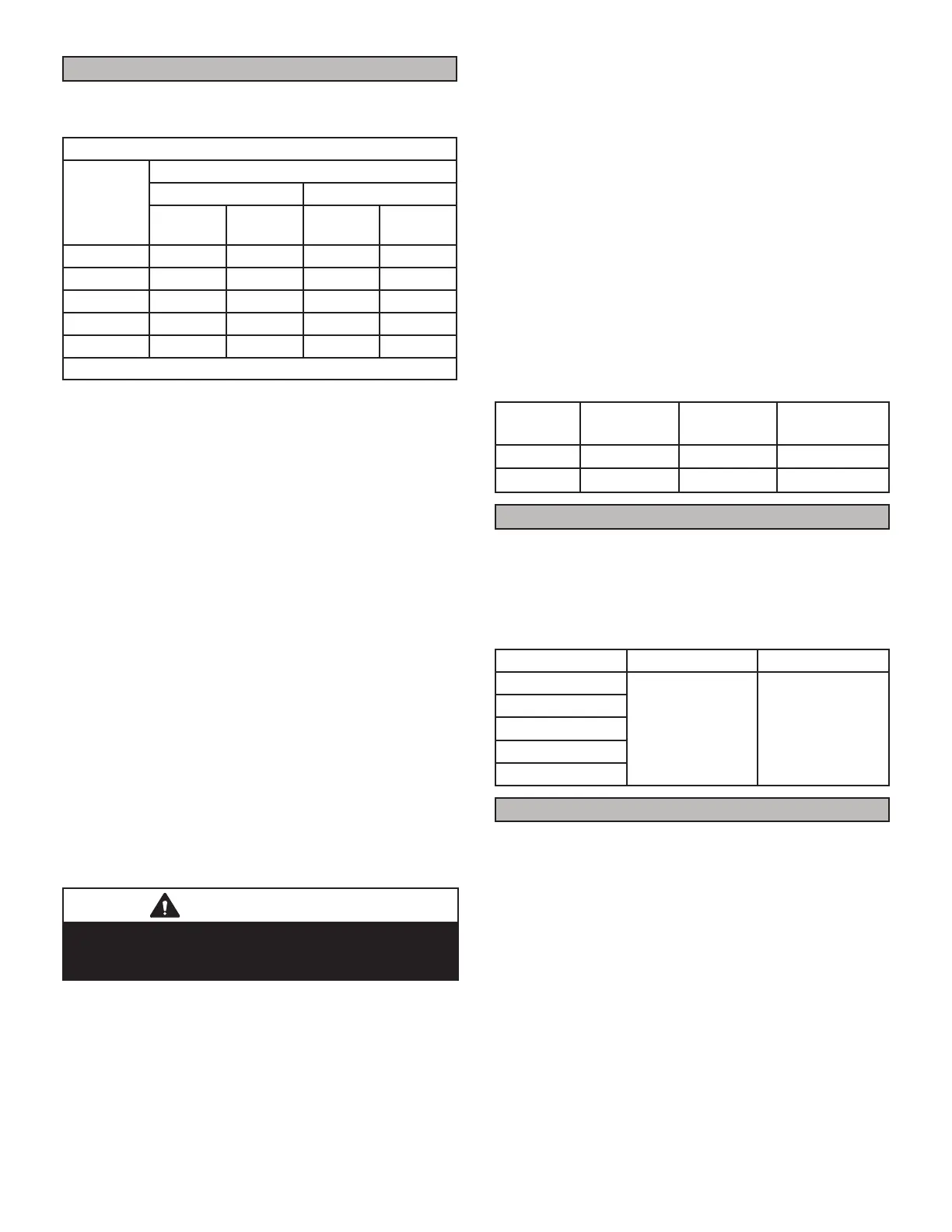
Gas Flow (Approximate)
TABLE 12
GAS METER CLOCKING CHART
EL196UHE
Unit
Seconds For One Revolution
Natuarl LP/Propane
1 cu ft
Dial
2 cu ft
Dial
1 cu ft
Dial
2 cu ft
Dial
-030 120 240 300 600
-045 80 160 200 400
-070 55 110 136 272
-090 41 82 102 204
-110 33 66 82 164
Natural-1000 btu/cu ft LP-2500 btu/cu ft
Furnace should operate at least 5 minutes before check-
LQJ JDV ÀRZ 'HWHUPLQH WLPH LQ VHFRQGV IRU WZR UHYROX-
tions of gas through the meter. (Two revolutions assures
a more accurate time.) Divide by two and compare to
time in TABLE 12. If manifold pressure matches TABLE
DQGUDWHLVLQFRUUHFWFKHFNJDVRUL¿FHVIRUSURSHUVL]H
and restriction. Remove temporary gas meter if installed.
NOTE - 7RREWDLQDFFXUDWHUHDGLQJVKXWR௺DOORWKHUJDV
DSSOLDQFHVFRQQHFWHGWRPHWHU
Supply Pressure Measurement
When testing supply gas pressure, use the 1/8” N.P.T.
plugged tap or pressure post located on the gas valve
WRIDFLOLWDWHWHVWJDXJHFRQQHFWLRQ6HH¿JXUH&KHFN
JDV OLQH SUHVVXUH ZLWK XQLW ¿ULQJ DW PD[LPXP UDWH /RZ
SUHVVXUHPD\UHVXOWLQHUUDWLFRSHUDWLRQRUXQGHU¿UH+LJK
pressure can result in permanent damage to gas valve or
RYHU¿UH
On multiple unit installations, each unit should be checked
separately, with and without units operating. Supply pres-
sure must fall within range listed in TABLE 13.
Check Manifold Pressure
After supply pressure has been checked and adjusted,
check manifold pressure. Move pressure gauge to outlet
pressure tap located on unit gas valve (GV1). Checks of
PDQLIROGSUHVVXUHDUHPDGHDVYHUL¿FDWLRQRISURSHUUHJ-
ulator adjustment.
IMPORTANT
)RU VDIHW\ FRQQHFW D VKXWRႇ YDOYH EHWZHHQ WKH
PDQRPHWHU DQG WKH JDV WDS WR SHUPLW VKXW Rႇ RI JDV
pressure to the manometer.
Follow the steps below. Gas manifold Kit 10L34 provides
additional components if needed.
1 - Connect the test gauge positive side “+“ to manifold
pressure tap on gas valve.
2 - Tee into the gas valve regulator vent hose and
connect to test gauge negative “-”.
3 - Start unit and let run for 5 minutes to allow for steady
state conditions.
$IWHUDOORZLQJXQLWWRVWDELOL]HIRU PLQXWHVUHFRUG
manifold pressure and compare to value given in
TABLE 13.
6KXWXQLWRႇDQGUHPRYHPDQRPHWHUDVVRRQDVDQ
accurate reading has been obtained. Take care to
replace pressure tap plug.
6 - Start unit and perform leak check. Seal leaks if found.
TABLE 13
Supply Line and Manifold Pressure (inches w.c.)
Unit Fuel
Manifold
Pressure
Line Pressure
All Nat 3.5 4.5 - 10.5
All LP/Propane 10.0
11.0 - 13.0
Proper Combustion
Furnace should operate minimum 15 minutes with correct
PDQLIROGSUHVVXUHDQGJDVÀRZUDWHEHIRUHFKHFNLQJFRP-
EXVWLRQ7DNH FRPEXVWLRQ VDPSOHEH\RQG WKH ÀXH RXWOHW
and compare to the table below. The maximum carbon
monoxide reading should not exceed 100 ppm.
TABLE 14
EL196 Unit CO2% Nat CO2% LP
-030
7.5- 8.5 8.2 - 9.5
-045
-070
-090
-110
High Altitude Information
127(,Q&DQDGDFHUWL¿FDWLRQIRULQVWDOODWLRQVDWHOHYD-
tions over 4500 feet (1372 m) is the jurisdiction of local
authorities.
Units may be installed at altitudes up to 10,000 ft. above
sea level. See table 16 for de-rate manifold values. Units
LQVWDOOHGDWDOWLWXGHRIIHHWUHTXLUHDQRUL¿FH
change. Units installed at altitude of 4501 - 10,000 feet
require a pressure switch change which can be ordered
separately. TABLE 16 lists conversion kit and pressure
switch requirements at varying altitudes.
The combustion air pressure switch is factory-set and re-
quires no adjustment.
 Loading...