Page 39
Electrical
ELECTROSTATIC DISCHARGE (ESD)
Precautions and Procedures
CAUTION
(OHFWURVWDWLFGLVFKDUJHFDQDႇHFWHOHFWURQLF
FRPSRQHQWV7DNHSUHFDXWLRQVWRQHXWUDOL]H
electrostatic charge by touching your hand
and tools to metal prior to handling the
control.
WARNING
(OHFWULF6KRFN+D]DUG&DQFDXVHLQMXU\RU
death. Unit must be properly grounded in
accordance with national and local codes.
WARNING
)LUH+D]DUG8VHRIDOXPLQXPZLUHZLWKWKLVSURGXFWPD\
UHVXOWLQD¿UHFDXVLQJSURSHUW\GDPDJHVHYHUHLQMXU\
or death. Use copper wire only with this product.
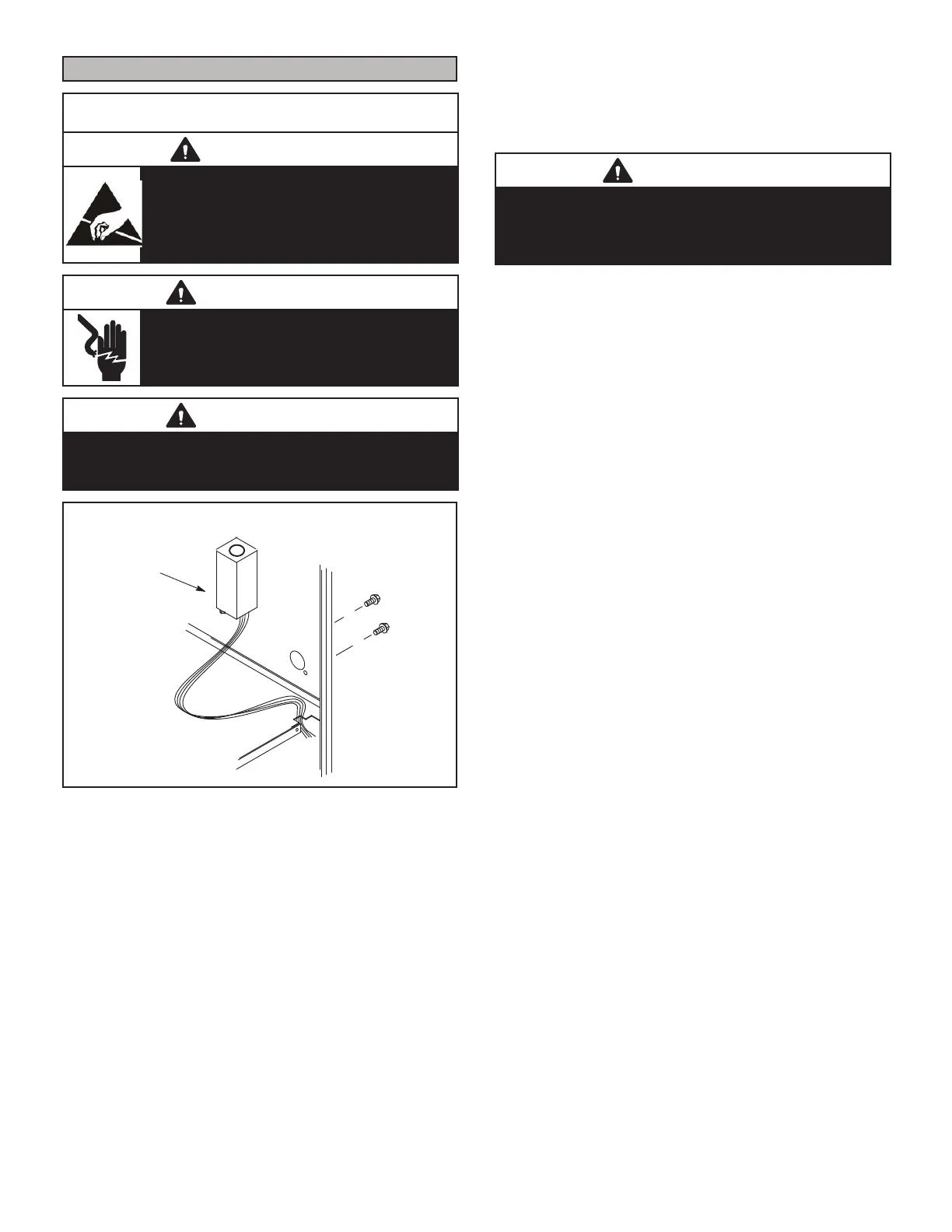
INTERIOR MAKE-UP BOX INSTALLATION
MAKE-UP
BOX
Right Side
Figure 58
7KHXQLWLVHTXLSSHGZLWKD¿HOGPDNHXSER[7KHPDNH-
up box may be moved to the right side of the furnace to fa-
cilitate installation. Secure the excess wire to the existing
harness to protect it from damage.
5HIHUWR )LJXUH IRU ¿HOGZLULQJVFKHPDWLF ZLULQJ GLD-
gram and troubleshooting.
The power supply wiring must meet Class I restrictions.
Protected by either a fuse or circuit breaker, select circuit
SURWHFWLRQDQGZLUHVL]HDFFRUGLQJWRXQLWQDPHSODWH
NOTE - 8QLW QDPHSODWH VWDWHV PD[LPXP FXUUHQW GUDZ
0D[LPXP2YHU&XUUHQW3URWHFWLRQDOORZHGLV$03
CAUTION
)DLOXUHWRXVHSURSHUO\VL]HGZLULQJDQGFLUFXLWEUHDNHU
PD\UHVXOWLQSURSHUW\ GDPDJH 6L]H ZLULQJ DQG FLUFXLW
EUHDNHUVSHU3URGXFW6SHFL¿FDWLRQVEXOOHWLQ(+%DQG
unit rating plate.
Holes are on both sides of the furnace cabinet to facilitate
wiring.
,QVWDOODVHSDUDWHSURSHUO\VL]HGGLVFRQQHFWVZLWFKQHDU
WKHIXUQDFHVRWKDWSRZHUFDQEHWXUQHGRႇIRUVHUYLFLQJ
Before connecting the thermostat check to make sure
the wires will be long enough for servicing at a later date.
Make sure that thermostat wire is long enough to facilitate
future removal of blower for service.
Complete the wiring connections to the equipment. Use
the unit wiring diagram shown in Figure 59. Use 18-gauge
wire or larger that is suitable for Class II rating for thermo-
stat connections.
Electrically ground the unit according to local codes or,
in the absence of local codes, according to the current
National Electric Code (ANSI/NFPA No. 70) for the USA
and current Canadian Electric Code part 1 (CSA standard
C22.1) for Canada. A green ground wire is provided in the
¿HOGPDNHXSER[
NOTE - 7KH(/8+(IXUQDFHFRQWDLQVHOHFWURQLFFRP-
SRQHQWVWKDWDUHSRODULW\VHQVLWLYH0DNHVXUHWKDWWKHIXU-
QDFHLVZLUHGFRUUHFWO\DQGLVSURSHUO\JURXQGHG
Accessory Terminals
One line voltage “EAC” 1/4” spade terminal is provided on
the furnace integrated control. See Figure 60 for integrat-
HGFRQWUROFRQ¿JXUDWLRQ7KLVWHUPLQDOLVHQHUJL]HGZKHQ
the indoor blower is operating. Any accessory rated up to
one amp can be connected to this terminal with the neutral
leg of the circuit being connected to one of the provided
neutral terminals. If an accessory rated at greater than
one amp is connected to this terminal, it is necessary to
use an external relay.
 Loading...