Page 33
External Operation (Speed Tap Priority)
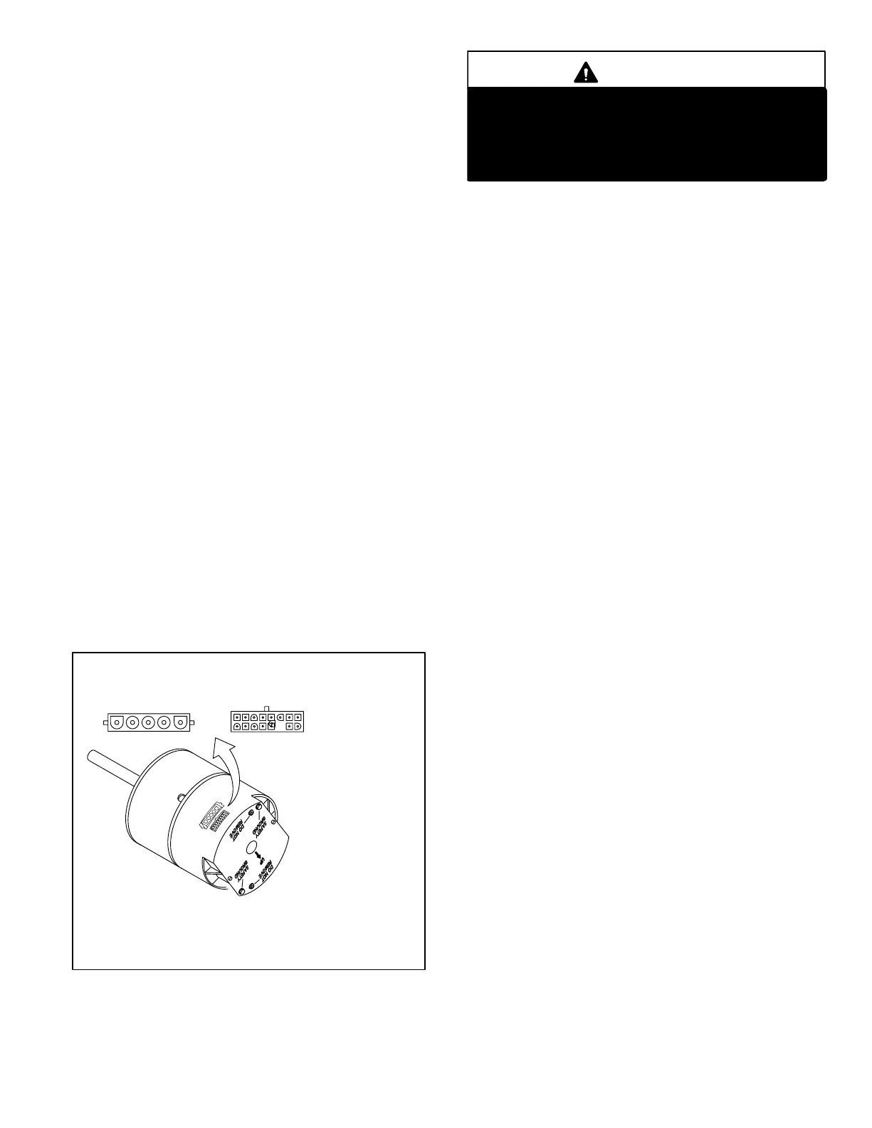
Figure 22 shows the two quick-connect jacks (J48 and J49)
which connect the motor to the G32V. Jack J48 is the power
plug and jack J49 connects the unit controls to the motor.
Line voltage must be applied to J48 pin 5 in order for the mo-
tor to operate. When using 120VAC pins 1 and 2 must be
jumpered. When control voltage is applied to J49 pin 3 and
15 (single stage heating and cooling), the motor is ener-
gized on the low speed heat/cool tap.
When voltage is applied to J49 pin 2 in addition to pin 3 and
15 (second stage heating), the blower is energized on the
high speed heating tap. When voltage is applied to J49 pin
10 in addition to pin 3 and 15 (second stage cooling), the
blower is energized on the high speed cooling tap. The motor
assigns priority to J49 pin 2 so that if a call for cooling and a call
for heating are concurrent, heating call overrides and the blow-
er operates on high speed heating tap.
ICM2 with VSP3 and Two Stage Variable Speed
Control
The ICM2 operates slightly different than stated above
when matched with the VSP3 control. When control voltage
is applied to J49 pin 3 and 15, the motor is energized on
continuous fan. When voltage is applied to J49 pin 2 in
addition to pin 3 and 15 (first stage heating), the blower is
energized on the low speed heating tap. When voltage is
applied to J49 pin 13 in addition to pin 3 and 15 (second
stage heating), the blower is energized on the high speed
heating tap. The motor assigns priority to J49 pin 2 so that if
a call for cooling and a call for heating are concurrent, heat-
ing call overrides and the blower operates on high speed
heating tap.
FIGURE 22
POWER
CONNECTOR J48
CONTROL
CONNECTOR J49
BLOWER B3 HARNESS CONNECTORS
J49
PIN 1 - C1
PIN 2 - W / W1
PIN 3 - C2
PIN 4 − Delay
PIN 5 - Cool
PIN 6 - Y1
PIN 7 - Adjust
PIN 8 - 0ut
PIN 9 - 0
PIN 10 - BK / PWM
PIN 11 - Heat
PIN 12 - R
PIN 13 - EM / W2
PIN 14 - Y / Y2
PIN 15 - G
PIN 16 - Out +
J48
PIN 1 - Jumper PIN 1 to PIN2 for 120VAC line input only.
PIN 2 - Jumper PIN 1 to PIN2 for 120VAC line input only.
PIN 3 - Ground
PIN 4 - AC Line
PIN 5 - AC Line
1
DANGER
Do not attempt to repair electronically controlled
blower motor or VSP. There are no field serviceable
parts. If either component appears to be faulty after
following checkout procedure, replace entire compo-
nent then recheck for proper operation.
2−Choke Coil (L13)
A choke coil is used on all G32V units. The choke is lo-
cated on the blower housing and is used to block radio fre-
quency interference.
Precautions
If the G32V or its electronically controlled blower motor is im-
properly or inadequately grounded, it may cause television in-
terference (commonly known as RFI or radio frequency inter-
ference).
This interference is caused by internal switching fre-
quencies of the motor controller. TV interference may
show up as small specks or lines which randomly appear
on the TV screen accompanied by pops or clicks in the sound.
Before attempting any service, make sure the indoor unit is
causing the interference. To check, disconnect power to indoor
unit then check TV for continued signs of interference.
TV interference may be stopped by making sure the mo-
tor is solidly grounded to the cabinet (metal to metal) and
by making sure the cabinet is solidly grounded. If TV inter-
ference persists, make sure the television (and all affected
RF appliances) are moved away from the G32V. Also make
sure affected appliances are connected to a separate electrical
circuit.
 Loading...


