Page 35
6.Gas Valve
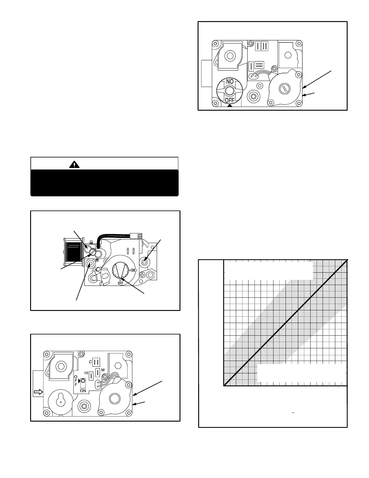
The G32V uses gas valves manufactured by White Rodg-
ers or Honeywell. The valves are two-stage internally re-
dundant to assure safety shut−off. If the gas valve must be
replaced, the same type valve must be used. The Honey-
well valve (figure 27) is adjustable on low fire and high fire
and is field convertible for LP. WhiteRodgers supplies two
separate valves for natural and LP (figures 28 and 29) .
White Rodgers valves are not adjustable on low fire.
24VAC terminals and gas control knob are located on top of the
valve. Terminals on the gas valve are connected to wires from
the SureLight integrated control and the two−stage control. 24V
applied to the terminals energizes the valve.
IMPORTANT
WhiteRodgers valve is NOT adjustable on low
fire. Do not attempt to adjust low fire on White-
Rodgers valve.
FIGURE 27
HONEYWELL VR8205 Series Gas Valve
GAS VALVE SHOWN IN OFF POSITION
MANIFOLD
PRESSURE
TAP
lOW FIRE
ADJUSTMENT
SCREW
(under cap)
INLET PRESSURE TAP
HIGH FIRE
ADJUSTMENT
SCREW
(under cap)
WHITE RODGERS 36E SERIES GAS VALVE
NATURAL GAS
HIGH HEAT
MANIFOLD
PRESSURE
ADJUSTMENT
ON SIDE
(under cap)
MANIFOLD
PRESSURE
OUTLET ON
SIDE
FIGURE 28
FIGURE 29
HI
C
PM
WHITE RODGERS 36E SERIES GAS VALVE
PROPANE GAS
HIGH HEAT
MANIFOLD
PRESSURE
ADJUSTMENT
ON SIDE
(under cap)
MANIFOLD
PRESSURE
OUTLET ON
SIDE
100% Sealed Combustion
The burner box is completely sealed and operates under a
negative pressure. A pressure hose is connected from the
burner box to the gas valve regulator and differential pres-
sure switch. The gas valve senses the pressure in the burn-
er box and changes gas valve output based on changes in
burner box pressure. The intent is to compensate for differ-
ent vent configurations which can greatly affect the rate of
the unit.
Figure 30 show how gas valve output changes as burner
box pressure changes. Generally, a lower burner box
pressure produces a leaner gas/air mixture and a higher
burner box pressure produces a richer mixture. Burner
box pressure pressure will be between 0" and −1.0". Man-
ifold pressure for natural units should be 3.5" W.C. + or −
.30" and 7.0" W.C. + or − .30" for propane units. A proce-
dure showing how to check manifold pressure is shown on
page 32.
BURNER BOX PRESSURE
(Negative inches water gauge
−1.0 −0.2 0−0.4−0.6−0.8
3.0
3.5
2.6
2.7
2.8
2.9
3.1
3.2
3.3
3.4
GAS VALVE OUTPUT
MANIFOLD PRESSURE (positive inches water column)
NORMAL OPERATION
measured on right side of burner box)
Gray area indicates normal operating range + 10% of manifold pres-
sure.The purpose of this chart is to explain unit operation . Each unit
may vary depending on installation, altitude, intake/exhaust configu-
ration and other factors.
AOPERATION AT THIS EXTREME
MAY INDICATE A BLOCKED
OUTLET OR OTHER PROBLEM
OPERATION AT THIS EXTREME
MAY INDICATE A BLOCKED
INLET OR OTHER PROBLEM"
FIGURE 30
2.5
 Loading...


