Page 40
2 − Secure all joints, including drain leg, gas tight using ap-
proved primer and cement.
3 − Piping diameters should be determined according to
length of pipe run. See vent pipe specifications on
page 6. Locate intake piping upwind (prevailing wind)
from exhaust piping. To avoid re−circulation of exhaust
gas on roof terminations, end of exhaust pipe must be
higher than intake pipe.
Exhaust and intake exits must be in same pressure
zone. Do not exit one through the roof and one on the
side. Also, do not exit the intake on one side and the
exhaust on another side of the house or structure.
4 − Intake and exhaust pipes should be placed as close to-
gether as possible at termination end (refer to illustra-
tions). Maximum separation is 3" (76mm) on roof ter-
minations and 6" (152mm) on side wall terminations.
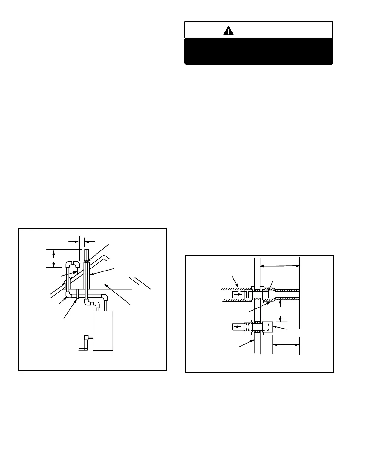
5 − Exhaust piping must terminate straight out or up as
shown. In rooftop applications, a 2" X 1−1/2" reducer for
2" venting, 3" x 2" reducer for 3" venting must be used
on the exhaust piping after it exits the structure to im-
prove the velocity of exhaust away from the intake pip-
ing.
On roof terminations, the intake piping should termi-
nate straight down using two 90 elbows (See figure
34).
FIGURE 34
ROOF TERMINATION KIT
(15F75) LB−49107CC for 2 (51) Venting
(44J41) LB−65678A for 3 (76) Venting
UNCONDITIONED
ATTIC SPACE
1/2 (13) FOAM
INSULATION IN
UNCONDITIONED
SPACE
3 x 2 (76 x 51) OR
2 x 1−1/2 (51 x 38)
PVC REDUCER
3(76) MAX.
12 (305) ABOVE
AVERAGE SNOW
ACCUMULATION
3 (76) OR
2 (51) PVC
PROVIDE SUPPORT
FOR INTAKE AND
EXHAUST LINES
8 (203) MIN
Inches(mm)
IMPORTANT
Do not use screens or perforated metal in intake
and exhaust terminations. Doing so will cause
freeze−ups and may block the terminations.
NOTE − If winter design temperature is below 32 F (0C), ex-
haust piping must be insulated with 1/2" (13mm), Armaflex or
equivalent when run through unheated space. Do not leave
any surface area of exhaust pipe open to outside air; exterior
exhaust pipe must be insulated with 1/2" (13mm) Armaflex or
equivalent. In extreme cold climate areas, 3/4" (19mm) Arma-
flex or equivalent is recommended. Insulation on outside runs
of exhaust pipe must be painted or wrapped to protect insula-
tion from deterioration.
NOTE − During extremely cold temperatures, below
approximately 20F (6.67C), units with long runs of vent
pipe through unconditioned space, even when insulated,
may form ice in the exhaust termination that prevents the
unit from operating properly. Longer run times of at least 5
minutes will help to alleviate most icing problems. Also, a
heating cable may be installed on exhaust piping and ter-
mination to prevent freeze−ups. Heating cable installation
kit is available from Lennox. See Condensate Piping sec-
tion for part numbers.
NOTE − Care must be taken to avoid re−circulation of ex-
haust back into intake pipe.
6 − On field supplied terminations for side wall exits, ex-
haust piping should extend a minimum of 12" (305mm)
beyond the outside wall. Intake piping should be as
short as possible. See figure 35.
FIGURE 35
1/2 (13) ARMAFLEX
INSULATION IN
UNCONDITIONED SPACE
2 (51) PVC 1−1/2 (38) PVC
12 (305) MIN.
2 X 1−1/2
(51 x 38)
PVC REDUCER
1/2 (13) ARMAFLEX
INSULATION
6 (152)
MAXIMUM
2 (51) PVC
COUPLING
8 (203)
MINIMUM
OUTSIDE
WALL
Inches (mm)
TOP VIEW
WALL RING KIT
(15J74) LB−49107CB for 2 (50.8) Venting
 Loading...


