Page 37
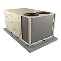
STANDARD BLOWER ASSEMBLY
TO INCREASE BELT TENSION
1- Loosen four bolts securing motor mounting base
to frame.
2- Turn adjusting bolt to the right, or clockwise, to
move the motor away from the blower housing.
IMPORTANT - Gap between end of frame and motor
mounting base should be equal at both ends, i.e. par
allel along gap.
3- Tighten four bolts securing motor mounting base
to frame.
4- Relieve tension on two adjusting bolts.
FIGURE 16
PULLEY
MOTOR
SIDE VIEW
ALLEN
SCREW
BELT ADJUSTING BOLTS
- TURN CLOCKWISE
TO TIGHTEN BELT
MOTOR MOUNTING
BASE
LOOSEN BEFORE
ADJUSTING BELT TENSION
(TWO EACH SIDE)
REMOVE TWO SCREWS ON EACH
SIDE TO SLIDE FRAME PARTIALLY
OUT OF UNIT FOR SERVICE ACCESS
MOTOR
BLOWER
HOUSING
BLOWER
FRAME
GAP BETWEEN
EDGES SHOULD BE
PARALLEL ON BOTH
ENDS BEFORE
TIGHTENING MOTOR
MOUNTING BASE IN
PLACE
REMOVE TWO SCREWS
TO COMPLETELY SLIDE
BLOWER OUT OF UNIT
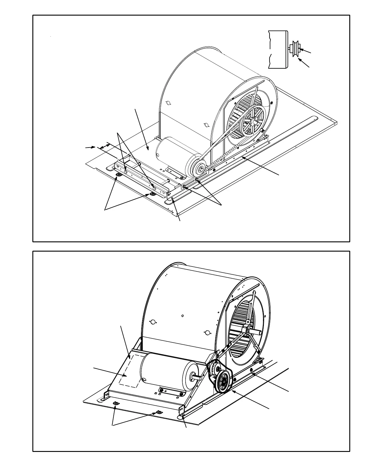
TENSIONER BLOWER ASSEMBLY (VIEW SHOWN WITHOUT BELT)
FIGURE 17
MOTOR
MOUNTING
BASE
REMOVE TWO SCREWS ON EACH
SIDE TO SLIDE FRAME PARTIALLY
OUT OF UNIT FOR SERVICE ACCESS
MOTOR
BLOWER
HOUSING
BLOWER
FRAME
TO COMPLETELY REMOVE
BLOWER ASSEMBLY FROM
UNIT, TWO ADDITIONAL
SCREWS MUST BE REMOVED
TO INCREASE OR
DECREASE BELT
TENSION, REFER TO
INSTALLATION LABEL
TENSIONER
 Loading...