Page 8
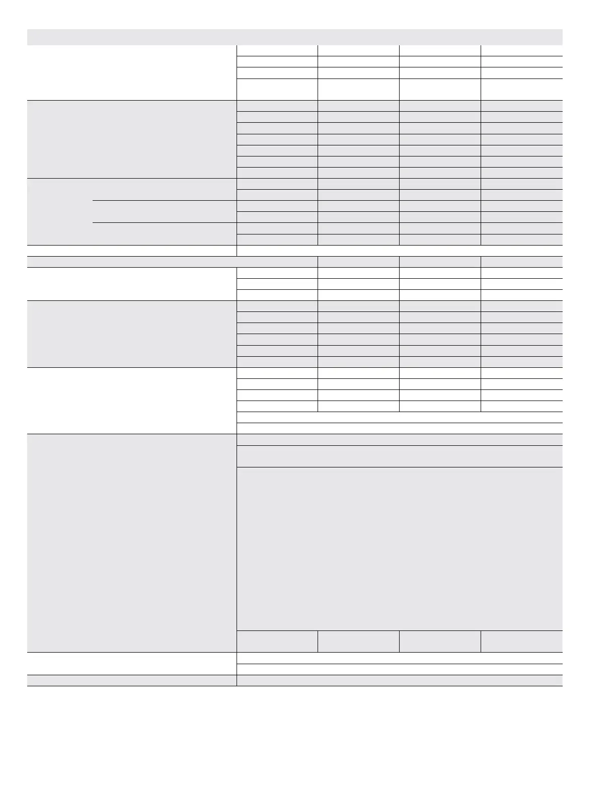
SPECIFICATIONS - 092H, 102H
General Data Nominal Tonnage 7.5 Ton 7.5 Ton 8.5 Ton 8.5 Ton
Model Number LGH092H4B LGH092H4M LGH102H4B LGH102H4M
Efciency Type High High High High
Blower Type Constant Air
Volume CAV
(Multi-Stage Air
Volume)
Constant Air
Volume CAV
(Multi-Stage Air
Volume)
Cooling
Performance
Gross Cooling Capacity - Btuh 93,000 93,000 103,800 103,800
1
Net Cooling Capacity - Btuh 90,000 90,000 100,000 100,000
AHRI Rated Air Flow - cfm 3000 2800 3400 3400
Total Unit Power - kW 7.5 7.5 8.1 8.1
1
EER (Btuh/Watt) 12.5 12.5 12.2 12.2
2
IEER (Btuh/Watt) 13.0 14.0 12.9 14.0
Refrigerant Type R-410A R-410A R-410A R-410A
Refrigerant
Charge
All-Aluminum Coil
System
Circuit 1 7 lbs. 8 oz. 7 lbs. 8 oz. 7 lbs. 8 oz. 7 lbs. 8 oz.
Circuit 2 7 lbs. 8 oz. 7 lbs. 8 oz. 7 lbs. 8 oz. 7 lbs. 8 oz.
Conventional Fin/Tube
Coil Option
Circuit 1 13 lbs. 8 oz. 13 lbs. 8 oz. 13 lbs. 8 oz. 13 lbs. 8 oz.
Circuit 2 12 lbs. 8 oz. 12 lbs. 8 oz. 12 lbs. 8 oz. 12 lbs. 8 oz.
Conventional Fin/Tube
With Humiditrol
®
Circuit 1 17 lbs. 0 oz. 17 lbs. 0 oz. 17 lbs. 0 oz. 17 lbs. 0 oz.
Circuit 2 12 lbs. 8 oz. 12 lbs. 8 oz. 12 lbs. 8 oz. 12 lbs. 8 oz.
Gas Heating Options Available - See page 10 Standard (2 Stage), Medium (2 Stage), High (2 Stage)
Compressor Type (number) Scroll (2) Scroll (2) Scroll (2) Scroll (2)
Outdoor Coils
Aluminum
(Fin/Tube)
Net face area (total) - sq. ft. 28.0 (29.33) 28.0 (29.33) 28.0 (29.33) 28.0 (29.33)
Number of rows 1 (3) 1 (3) 1 (3) 1 (3)
Fins per inch 20 (20) 20 (20) 20 (20) 20 (20)
Outdoor
Coil Fans
Motor - (No.) hp (2) 1/3 (2) 1/3 (2) 1/3 (2) 1/3
Motor rpm 1075 1075 1075 1075
Total Motor watts 800 800 800 800
Diameter - (No.) in. (2) 24 (2) 24 (2) 24 (2) 24
Number of blades 3 3 3 3
Total Air volume - cfm 8800 8800 8800 8800
Indoor
Coils
Net face area (total) - sq. ft. 12.78 12.78 12.78 12.78
Tube diameter - in. 3/8 3/8 3/8 3/8
Number of rows 4 4 4 4
Fins per inch 14 14 14 14
Drain connection - Number and size (1) 1 in. NPT coupling
Expansion device type Balance port TXV, removable head
3
Indoor
Blower and
Drive
Selection
Nominal motor output 2 hp, 3 hp, 5 hp
Maximum usable motor output
(US Only)
2.3 hp, 3.45 hp, 5.75 hp
Motor - Drive kit number 2 hp
Kit 1 590-890 rpm (std. and high efciency)
Kit 2 800-1105 rpm (std. and high efciency)
Kit 3 795-1195 rpm (std. and high efciency)
3 hp
Kit 4 730-970 rpm (std. efciency)
Kit 5 940-1200 rpm (std. efciency)
Kit 6 1015-1300 rpm (std. efciency)
Kit 7 730-970 rpm (high efciency)
Kit 8 940-1200 rpm (high efciency)
Kit 9 1015-1300 rpm (high efciency)
5 hp
Kit 10 900-1135 rpm (std. efciency)
Kit 11 1040-1315 rpm (std. efciency)
Kit 12 1125-1425 rpm (std. efciency)
Blower wheel nominal diameter x
width - in.
(1) 15 X 15 (1) 15 X 15 (1) 15 X 15 (1) 15 X 15
Filters Type of lter Disposable
Number and size - in. (4) 20 x 25 x 2
Electrical characteristics 208/230V, 460V or 575V - 60 hertz - 3 phase
NOTE - Net capacity includes evaporator blower motor heat deduction. Gross capacity does not include evaporator blower motor heat deduction.
1
AHRI Certied to AHRI Standard 340/360; 95°F outdoor air temperature and 80°F db/67°F wb entering evaporator air; minimum external duct static pressure.
2
Integrated Energy Efciency Ratio certied and tested according to AHRI Standard 340/360.
3
Using total air volume and system static pressure requirements determine from blower performance tables rpm and motor output required. Maximum usable output of
motors furnished are shown. In Canada, nominal motor output is also maximum usable motor output. If motors of comparable output are used, be sure to keep within
the service factor limitations outlined on the motor nameplate.
NOTE – Units equipped with Multi-Stage Air Volume option are limited to a motor service factor of 1.0.