Page 55
IV-START-UP - OPERATION
Refer to start-up directions and to the unit wiring diagram
when servicing. See unit nameplate for minimum circuit
ampacity and maximum fuse size.
A-Preliminary and Seasonal Checks
1- Make sure the unit is installed in accordance with the
installation instructions and applicable codes.
2- Inspect all electrical wiring, both field and factory installed
for loose connections. Tighten as required. Refer to unit di
agram located on inside of unit control box cover.
3- Check to ensure that refrigerant lines are in good
condition and do not rub against the cabinet or other
refrigerant lines.
4- Check voltage. Voltage must be within the range listed
on the nameplate. If not, consult power company and
have the voltage corrected before starting the unit.
5- Recheck voltage and amp draw with unit running. If
voltage is not within range listed on unit nameplate,
stop unit and consult power company. Refer to unit
nameplate for maximum rated load amps.
6- Inspect and adjust blower belt (see section on Blower
Compartment - Blower Belt Adjustment).
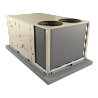
B-Cooling Start-up See figure 34, 35 or 36
for Circuits
NOTE-Crankcase heaters must be energized 24 hours be
fore attempting to start compressor. Set thermostat so that
there is no demand to prevent compressor from cycling.
Apply power to unit.
FIGURE 34
REFRIGERANT STAGES -
All-Aluminum Coil
1
2
(BOTH FANS ARE ENERGIZED
WITH A Y1 DEMAND)
EVAPORATOR
COIL STAGE 1
EVAPORATOR
COIL STAGE 2
CONDENSER
COIL STAGE 2
CONDENSER
COIL STAGE 1
CONDENSER
FAN STAGE 1
CONDENSER
FAN STAGE 2
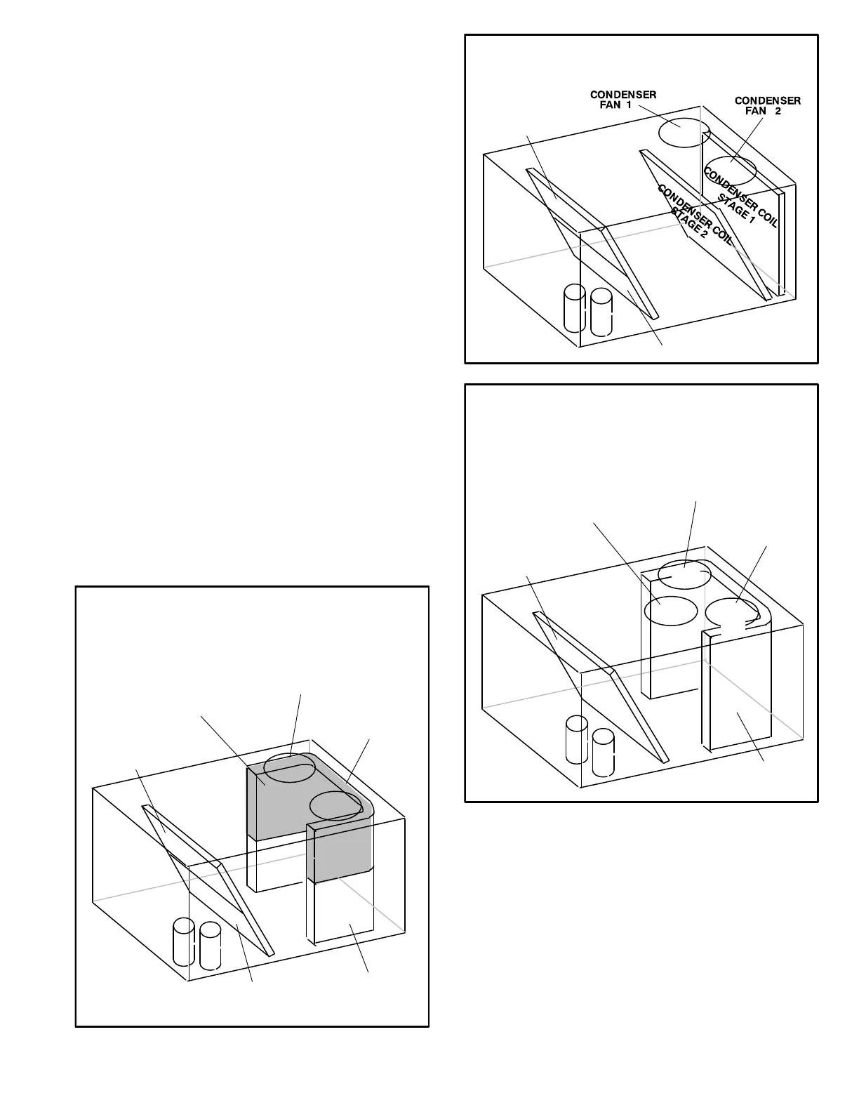
FIGURE 35
REFRIGERANT CIRCUITS -
Fin/Tube Coil
1
2
(BOTH FANS ARE ENERGIZED
WITH A Y1 DEMAND)
EVAPORATOR
COIL STAGE 1
EVAPORATOR
COIL STAGE 2
1
2
(ALL FANS ARE ENERGIZED IN LOW SPEED WITH A Y1
DEMAND AND HIGH SPEED WITH A Y2 DEMAND)
EVAPORATOR
COIL
OUTDOOR
COIL
OUTDOOR
FAN 2
OUTDOOR
FAN 3
B2
1
REFRIGERANT STAGES - 094U, 122U, 152U
TRADITIONAL FIN/TUBE COIL
B4
OUTDOOR
FAN 1
B5
FIGURE 36
VFD Units - Refer to the Supply Air Inverter Start-Up section.
1- Initiate first and second stage cooling demands ac
cording to instructions provided with thermostat.
2- First-stage thermostat demand will energize compres
sor 1. Second-stage thermostat demand will energize
compressor 2.
3- Standard and high efficiency units contain two refriger
ant circuits or stages. Ultra high efficiency units have
one common (tandem) refrigerant circuit.
4- Each refrigerant circuit is separately charged with
refrigerant. See unit rating plate for correct amount
of charge.
 Loading...