6
Back cover
Prying
position
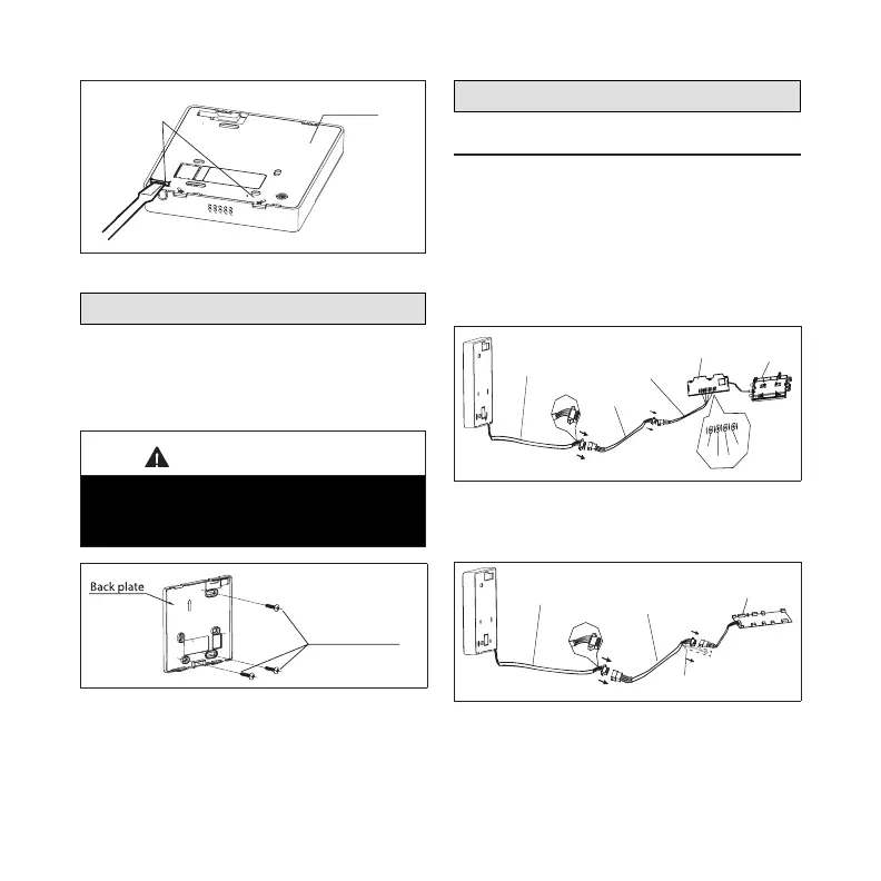
Figure 2. Back Plate Removal
Installing Back Plate
When installing the back plate to a at drywall
surface, use the provided screws for securing
the back plate to the drywall (ST3.9*25). Wall
anchors are provided for use, if necessary.
IMPORTANT
Always install the back plate on a at
surface. Do not distort back plate by over-
tightening the mounting screws.
3 screws (ST3.9*25)
Figure 3. Securing Back Plate to
Drywall
Making Connections
Cable Connection Illustration
1. Connect the controller 4-pin shielded
cable assembly to the 4-pin shielded
extension cable.
2. Connect the 4-pin shielded extension
cable to the adapter board, which
connects to the display board.
4-core wire
Adaptor board
Display board
The connection cable A
X
Y
E
5V/12V
White
Yellow
Brown
Red
The connection cable D
Figure 4. Connection Cable D for
MWMC, MWHB, and MWCB Wall
Mounted Models
4-core wire
The connective wires group
shielded wire(some units)
Mainboard
Figure 5. Connection Cable for
MMDA/B, MCFA/B, M22A and M33A/
B/C Indoor Units

 Loading...