Page 49
10. Discharge Air Control
10.1. Cooling
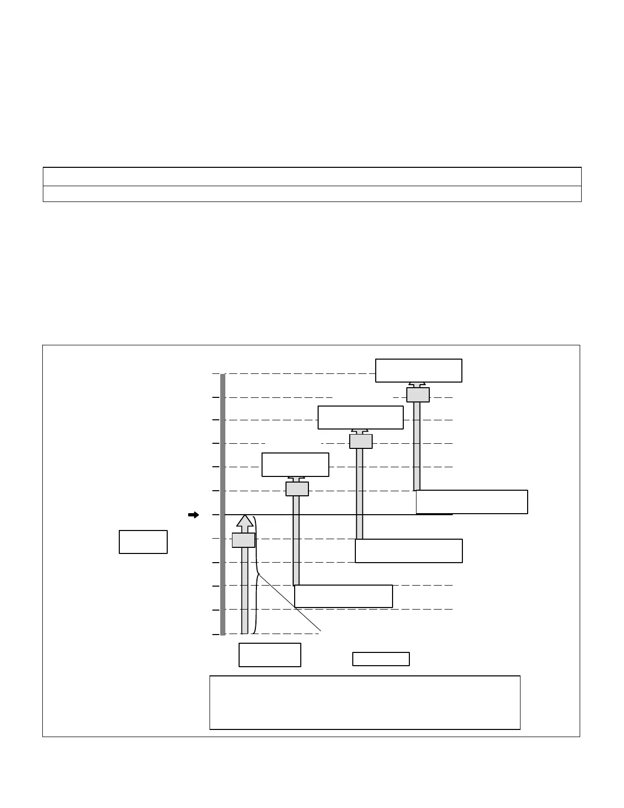
The discharge air control cooling option automatically cycles up to 4-stages of cooling to maintain a discharge air control
cooling set point.
When an economizer is installed, adjust free cooling set point Parameter 159 approximately 2 degrees lower than
Discharge Air Control Cooling set point. This will allow free cooling to operate before Discharge Air Control Cooling
energizes compressors.
Refer to figure 13 for Discharge Air Control Cooling cooling stages.
Adjust Parameter 111 to option 4 to enable discharge air control cooling.
IMPORTANT
Discharge air sensor RT6 must be moved to the supply air duct, preferably after a 90 degree branch of the main duct.
Discharge Air Control Cooling is initiated by an input in one of three ways:
1. Y1 input from an external device— If the M3 Unit Controller is configured for wired thermostat.
Go to SETTINGS > CONTROL > CONTROL TYPE = WIRED THERMOSTAT.
2. Cooling demand while in RTU STANDALONE mode:
Go to SETUP > NETWORK INEGRATION > NETWORK = RTU STANDALONE > OCC BLOWER MODE = > BACK
UP MODE = > and continue to answer questions concerning heating and cooling setpoints.
3. Cooling demand while in room sensor mode:
Go to SETUP > NETWORK INEGRATION > NETWORK = (L CONNECTION, LONTALK OR BACNET) > any
additional network settings > CONTROL MODE = ROOM SENSOR > and continue to answer questions concerning
network sensor type, OCC blower mode and backup mode.
56
57
58
59
60
61
55
54
53
55°F Default Occupied
Discharge Air Control
Cooling Set point
C1
ON
OFF
55°F - 5°F
Parameter 180 -
Parameter 182
Parameter 181 Unoccupied DACC_SP
Parameter 183 DAC Cooling Stage-Up Delay 3 minutes
Parameter 184 DAC Cooling Stage-Down Delay 2 minutes
Compressor Minimum Off or Run Times Apply
52
51
50
5°F Discharge Air Cooling Control
Dead-band (All Stages Same Setting)
C2
ON
OFF
55°F + 2°F Diff
Parameter 180 +
Parameter 185
55°F + 2°F - 5°F
Parameter 180 + Parameter
185 - Parameter 182
ON
OFF
55°F + 4°F Diff.
Parameter 180 + (Para
meter 185 X 2)
C4
ON
OFF
55°F + 6°F Diff.
Parameter 180 + (Para
meter 185 X 3)
C3
55°F + (2°F X 2) -5°F
Parameter 180 + ( Parameter
185 X 2) - Parameter 182
55°F + (2°F X 3) - 5°F
Parameter 180 + (Parameter 185
X 3) - Parameter 182
Parameter 182
Parameter
180
C1 = Cooling Stage 1
C2 = Cooling Stage 2
C3 = Cooling Stage 3
C4 = Cooling Stage 4
Figure 13. Discharge Air Control Cooling Stages - Default Values Shown

 Loading...


