5
Wiring Diagrams
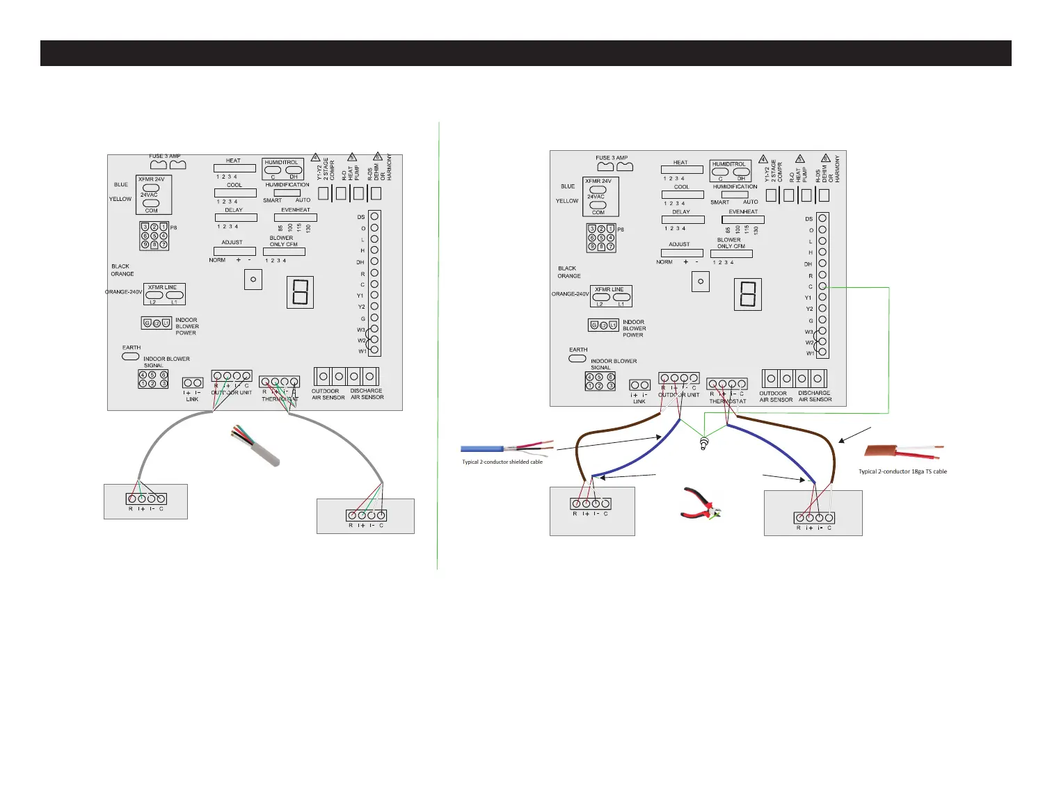
Communication Wiring Options
OPTION 1
Lennox Communicating
Outdoor Unit
Lennox Communicating
Thermostat
Cut shield off at this end
Indoor Unit Communicating Control
(Using Shielded Wiring for Communication Lines)
18AWG
unshielded **
Shield (drain) wire MUST
be connected to indoor unit
common terminal.
OPTION 2
18 or 22AWG
shielded
Lennox Communicating
Outdoor Unit
Lennox Communicating
Thermostat
18 or 22AWG
Standard Thermostat
Cable (4-Conductor)
Indoor Unit Communicating Control
(Using Non-Shielded Wiring)
Figure 3. Lennox Communicating System Wiring Connections using Unshielded (Option 1) or Shielded Wiring (Option 2) Cabling
There may be situations where alternate wirings methods may need to be employed. Two options are available to address an inductive voltage issue. If Alert
Code 105 (see “Table 20. Service Alert Notication Codes” on page 45) is still present after following troubleshooting Steps 1 and 2 then proceed to Step 3
wiring options 2 or 3.
• Option 2 - Using shielded 2-conductor cable between the indoor, outdoor and thermostat -i and +i terminals may be required.
• Option 3 - Using unshielded 2-conductor cable between the indoor, outdoor and thermostat -i and +i terminals may be required.
NOTE: When using multi-conductor unshielded thermostat cable, refer to “Figure 5. Minimizing Electrical Noise” on page 6.
 Loading...