Mechanical installation
Mounting of g500 short/servo adapters with clamping connection
Attachment of gearboxes with hollow shafts and keyway
4
24
Lenze ¯ MA 12.0018 ¯ 2.0
4.4.4.2 Disassembly of clamping ring hub
1. Loosen the clamping screws evenly one after the other.
Stop!
Each screw must only be loosened by half a revolution per pass! Unscrew
all clamping screws by 3 − 4 threads.
2. Remove the screws next to the forcing threads and screw them into the other
threads until they have contact.
3. Tighten the screws in the forcing threads crosswise and step−by−step so that the
clamping ring is loosened.
4. Clean and grease all contact surfaces including threads and head of the clamping
screws before reassembly.
4.4.5 Attachment of gearboxes with hollow shafts and keyway
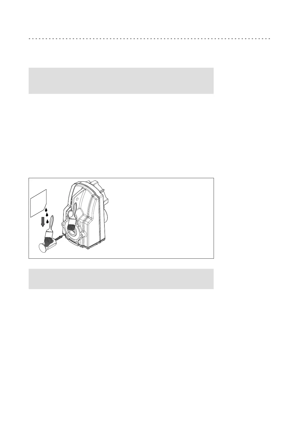
1. Draw the gearbox with hollow shaft onto the machine shaft to be driven:
– Apply fitting grease (Fig. 9) to the shaft and into the hollow shaft bore.
1.
4.
3.
L
Paste gegen
Passungsrost
2.
Fig. 9 Application of fitting grease against fretting corrosion (can be ordered optionally)
Stop!
Take up forces only via the hollow shaft, and not via gearbox housing.
2. Secure the gearbox axially:
– The hollow shaft has snap ring grooves for axial securing. Parts used to fix the
shaft are not included in the scope of supply.
 Loading...