Mechanical installation
Mounting of g500 short/servo adapters with clamping connection
Foot mounting
4
31
Lenze ¯ MA 12.0018 ¯ 2.0
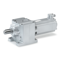
4.4.9 Foot mounting
The foot on the g500−S130 S660 gearboxes can be mounted in three positions (3, 4,
5) using the supplied screws. It is mounted on side 6 using 4 screws and additionally on
side 1 using 2 screws. The screws must be mounted according to the hole pattern on the
foot (see figure) depending on the foot position.
Mounting order: depending on the mounting situation and installation space, the foot
can first be screwed to the machine housing and then to the gearbox or vice versa. The
foot can be mounted to the machine using studs or screws (not included in the scope of
supply).
Aligning the gearbox with the foot: independent of the mounting order, the gearbox
must be aligned with the machine shaft.
Gearbox Tightening torque
Code Type [Nm]
G50BS113 + G50BS122 g500−S130 + g500−S220 10
G50BS140 + G50BS166 g500−S400 + g500−S660 48
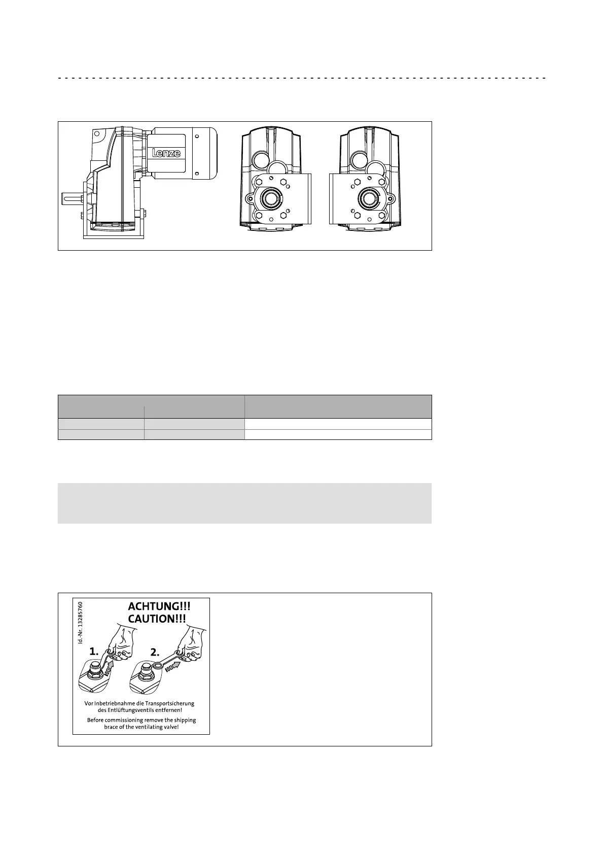
4.4.10 Gearboxes with breathers
Stop!
Do not place gearbox onto breather valve!
No ventilation measures are required for the gearboxes g500−S130 and g500−S220.
Gearboxes which are delivered with a ventilation unit are equipped with a label on the
gearbox.
Remove the transport locking device on the vent valve before the first commissioning.
GT−GNG−13285760.iso/dms
 Loading...