Connecon via ICN connector
In order to provide for a quick and error-free connecon of Lenze motors to
Lenze inverters, we recommend using prefabricated Lenze system cables.
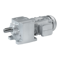
Posion of the connecons
Posion Meaning Note
1 ICN-M23 connector, 6-pole
•
Power connecon
•
Brake connecon
•
PE connecon
When ordering, specify the mounng posion of the connector:
•
Shown here: "T"
•
Opposite "L
In addion to connector ICN-M23, 8-pole:
•
Connecon of TKO temperature monitoring
Cauon:
Max. brake supply voltage ≤ 230 V
2 ICN-M23 connector
•
Feedback connecon
•
Connecon of PT1000 temperature sensor
The mounng posion of the feedback connector is located on
the opposite side from the power connecon (posion L/R).
3 ICN-M17 connector
•
Blower connecon
When ordering, specify the mounng posion of the terminal
box:
•
Shown here: "T"
•
L, R or B
If required, the terminal box can be rotated step by step by 90 °
aer loosening the screws in the terminal box.
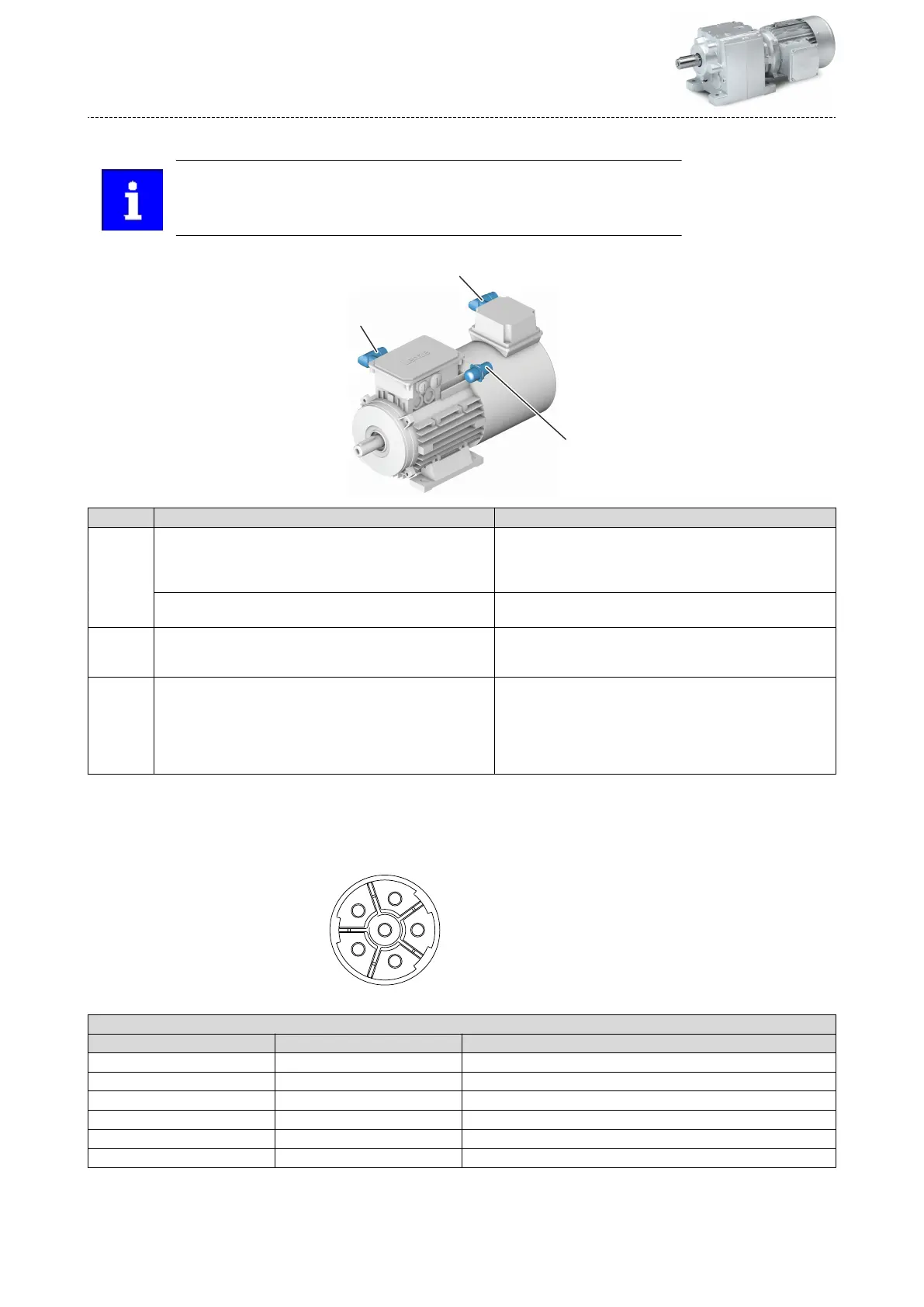
Power and brake connecon
ICN-M23 connector assignment
6-pole
ICN M23 6-pole
Contact Name Meaning
1 BD1 DC +/AC brake
2 BD2 DC -/AC brake
PE PE PE conductor
4 U Power phase U
5 V Power phase V
6 W Power phase W
Product extensions
Motor connecon
Connecon via ICN connector
134
 Loading...