Communication manual 8400 motec CANopen
Installation
Electrical installation
24 L EDS84DMOTCAN EN 3.0 - 11/2011
5.2 Electrical installation
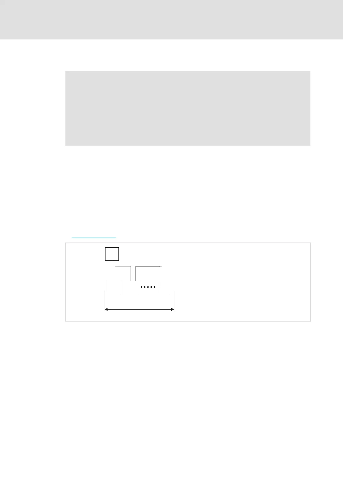
5.2.1 Network topology
The following examples show two simple CAN networks.
Each segment of the network must be terminated at both ends by resistors (120 Ω)
between CAN-Low and CAN-High. The bus terminators of the system bus (CAN) are marked
with a "Z" in the following examples.
A CAN network consisting of only one segment starts with the CAN master (M) with
integrated bus termination, whereas the last CAN node (S) has to be terminated by a bus
terminating resistor.
Bus termination
( 25)
[5-2] CAN network with one segment
"Inverter Drives 8400 motec" hardware manual
Here you'll find detailed information on ...
• the digital and analog inputs and outputs;
• the relay output;
• the integrated safety system (safety option);
• the wiring of the connections.
Observe the notes and wiring instructions given in the documentation.
E94YCPM012a
M
Z
Z
S SS
1
 Loading...