25
EDBSV571 EN 1.0
EN
Commissioning
4.5.3 Advanced Setup Parameters
Code Possible Settings
IMPORTANT
No. Name Default Selection
P165
Base Voltage 15 {V} 1000 Valid for V/Hz mode only.
Set voltage for bus compensation in V/Hz
mode
P166
Carrier Frequency 0 0 4 kHz • As carrier frequency is increased, motor
noise is decreased
• Observe derating in section 2.3
• Automatic shift to 4 kHz at 120% load
• NEMA 4X (IP65) Models: Default = 0 (4kHz)
• NEMA 1 (IP31) Models: Default = 1 (6kHz)
1 6 kHz
2 8 kHz
3 10 kHz
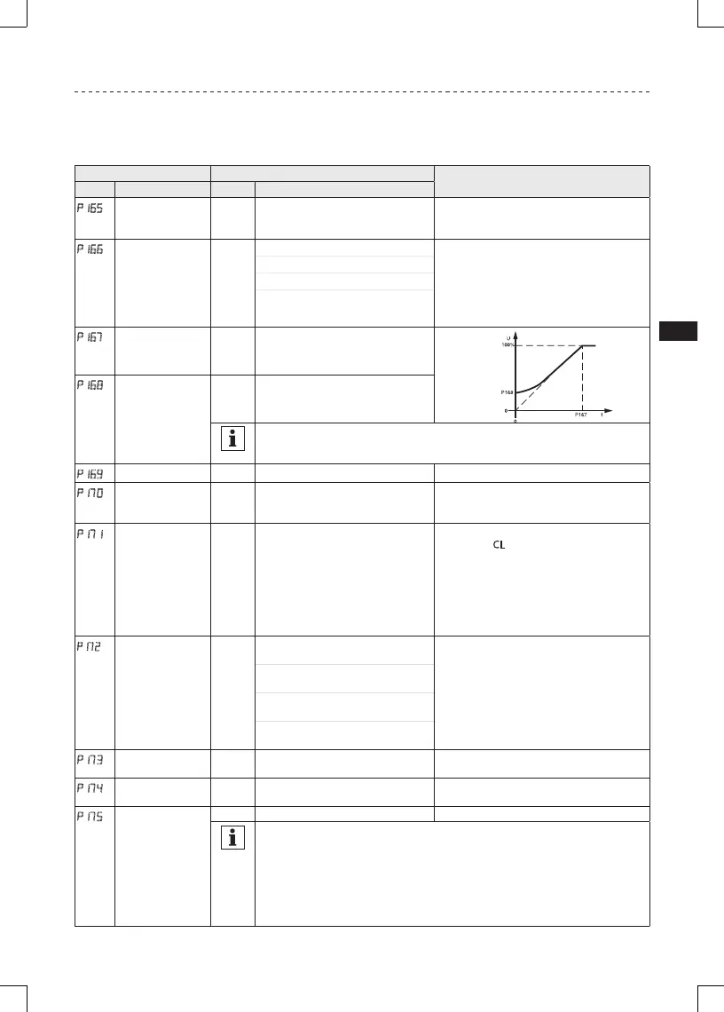
p167
(1)
Base Frequency 60.0 10.0 {Hz} 1500
V0112
p168
Fixed Boost 0.0 {%} 40.0
NOTE
• P167 = rated motor frequency for standard applications
• P165, P168 = default setting depends on drive rating
p169
Accel Boost 0.0 0.0 {%} 20.0 Accel Boost is only active during acceleration
P170
Slip Compensation 0.0 0.0 {%} 40.0 Increase P170 until the motor speed no
longer changes between no load and full load
conditions.
p171
(1)
Current Limit Max I 30 {%} Max I • When the limit is reached, the drive
displays CL(Current Limit), and either the
acceleration time increases or the output
frequency decreases.
• Digital outputs can also indicate when the
limit is reached; see P140, P142.
• Refer to section 2.3 for the maximum
output current Max I (%)
P172
Current Limit
Reduction
0 0 Current Limit Reduction Active -
Normal response
In field weakening, the Current Limit is
inversely proportional to the speed.
1 Current Limit Reduction Active -
Fast response
2 Current Limit Reduction Disabled
- Normal response
3 Current Limit Reduction Disabled
- Fast response
P173
Decel Override
Time
2.0 0.0 {s} 60.0 Maximum time before drive trips into HF
fault.
P174
DC Brake Voltage 0.0 0.0 {%} 50.0 Setting is a percent of the nominal DC bus
voltage.
p175
DC Brake Time 0.0 0.0 {s} 999.9
NOTE: CONFIRM MOTOR SUITABILITY FOR USE WITH DC BRAKING
DC Brake voltage (P174) is applied for the time specified by P175 with the following
exceptions:
• If P111=1, 3 and P175=999.9 the brake voltage will be applied continuously until a
run or fault condition occurs.
• If P110=2, 4…6 and P175=999.9, brake voltage will be applied for 15s
• If P121…P124=18 and the corresponding TB-13 input is CLOSED, brake voltage will
be applied until the TB-13 input is OPENED or a fault condition occurs.
 Loading...