34
EDBSV571 EN 1.0
EN
Commissioning
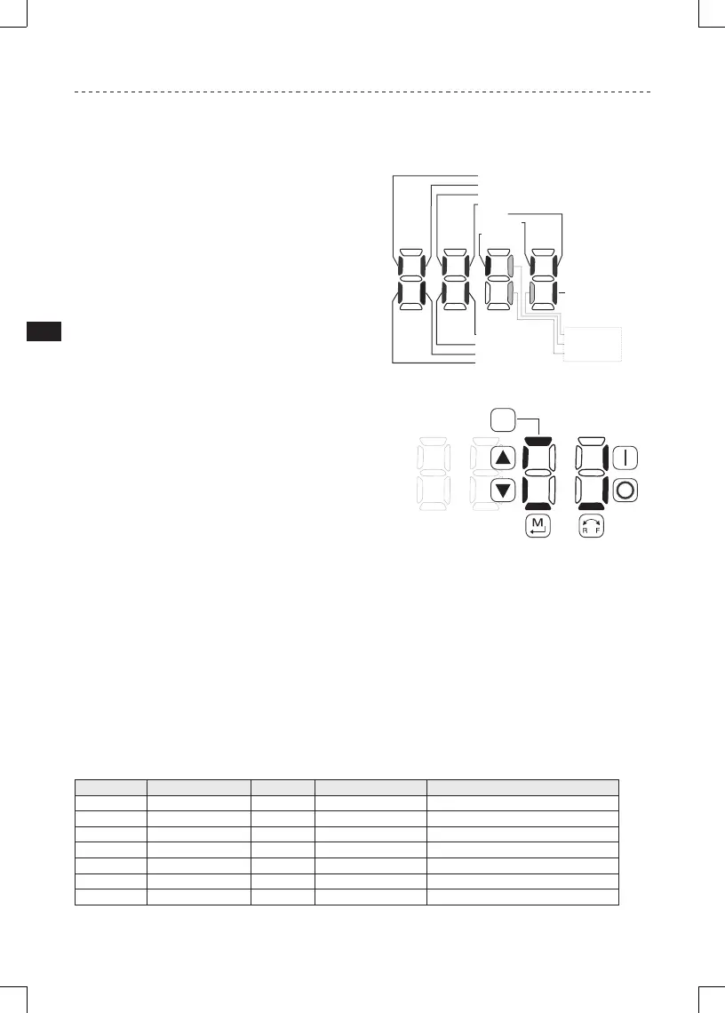
4.5.7.1 Terminal & Protection Status Display
Parameter P530 allows monitoring of the control
terminal points and common drive conditions:
An illuminated LED segment indicates:
• the protective circuit is active (LED 1)
• the Logic Assertion Switch is set to High (+)
• input terminal is asserted (LED 2)
• output terminal is energized (LED 4)
• the Charge Relay is not a terminal, this
segment will be illuminated when the
Charge Relay is energized (LED 4).
Input 13C
Input 13A
Factory Reserved
Protective Diagnostic
Logic Assertion Switch
Input 1
Input 13B
Relay
Output 14
Input 13D*
* Input 13D available on 15-60HP (11-45kW) models only
LED
#
12
3
4
Charge
Relay
Auxiliary Relay
Input 13F
Input 13E
Additional I/O Module only
4.5.7.2 Keypad Status Display
Parameter P531 allows monitoring of the keypad
pushbuttons:
An illuminated LED segment indicates when the button is
depressed.
LED 1 and LED 2 are used to indicate pushbutton presses
on a remote keypad that is attached to the drive. LED
3 and LED 4 indicate button presses on the local drive
keypad.
CTRL
4.5.8 Custom Modbus Instructions for ESVxxxNxxxXB571 models
Control scheme, new register area and control word has been implemented.
Legacy control scheme utilizing: writing to special registers 48 and 49 to ‘unlock’ control and parameters is
not supported any more in these drives. Legacy control register is no longer supported as well. Requirement
for one of the digital input terminals to be asserted with its selection set to ‘Network Enabled’ has been
removed.
To simplify access and control, new register area has been implemented starting at reg. address 2000. In
this special range, multiple registers access is supported.
Automatic Restarts (power up starts) are working only if P110 is set to one of the restarts settings and:
P100 = 1 (Terminal mode); P121 = 0 or 1; and terminal Tb1 is asserted.
Modbus Reg. Name Access Type Range of adjustment Important
2000 Drive Status Word Read only 0 – 0xFFFF
See bit details below
2001 Actual Frequency Read only 0 – 65535 [0.1Hz] Resolution 0.1Hz (ex. 345 – 34.5Hz)
2002 Drive Fault Code Read only 0-255 See details below
2003 Drive State Read only 0 – 255 See details below
2004 Motor Voltage Read only 0 – 1000 [VAC] RMS voltage applied to Motor (P506)
2005 Motor Current Read only 0-1000 [0.1A] Motor phase current (P508)
 Loading...