41
EDBSV571 EN 1.0
EN
Troubleshooting and Diagnostics
5.2 Drive Configuration Messages
When the Mode button is pressed and held, the drive’s display will provide a 4-digit code that indicates how
the drive is configured. If the drive is in a Stop state when this is done, the display will also indicate which
control source commanded the drive to Stop (the two displays will alternate every second).
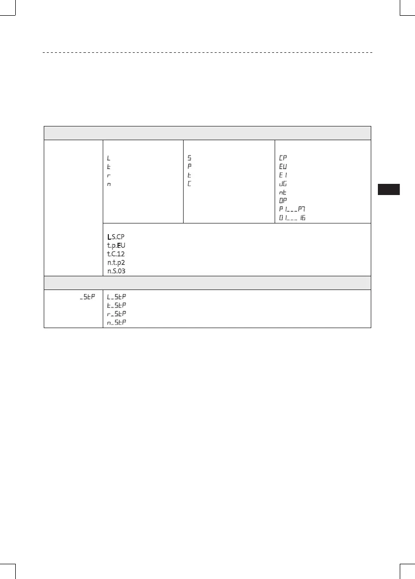
Configuration Display
Format = x.y.zz x = Control Source:
L = Local Keypad
t = Terminal Strip
r = Remote Keypad
n = Network
y = Mode:
S = Speed mode
P = PID mode
t = Torque mode
C = Sequencer mode
zz = Reference:
CP = Keypad p q
EU = 0-10 VDC (TB-5)
E1 = 4-20 mA (TB-25)
JG = Jog
nt = Network
OP = MOP
P1...P7 = Preset 1...7
01...16 = Sequencer Segment
Example:
L.S.CP = Local Keypad Start control, Speed mode, Keypad speed reference
t.p.EU = Terminal Strip Start control, PID mode, 0-10 VDC setpoint reference
t.C.12 = Terminal Strip Start control, Sequencer Operation (Speed mode), Segment #12
n.t.p2 = Network Start control, Vector Torque mode, Preset Torque #2 reference
n.S.03 = Network Start control, Speed mode, Speed reference from Sequencer segment #03
Stop Source Display
Format = x.StP L.stp = Stop command came from Local Keypad
t.stp = Stop command came from Terminal Strip
r.stp = Stop command came from Remote Keypad
n.stp = Stop command came from Network
 Loading...