 Loading...
Do you have a question about the LG CM8460 and is the answer not in the manual?
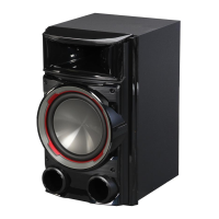
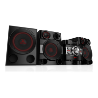
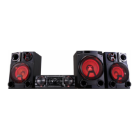
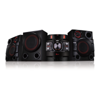
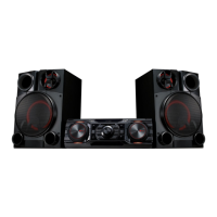
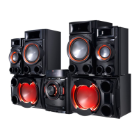
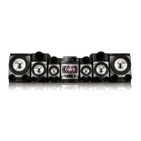
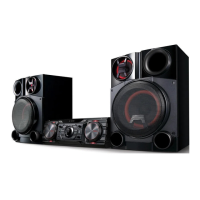
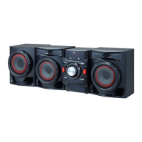
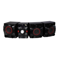
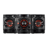
| Type | Home audio mini system |
|---|---|
| Cassette deck | - |
| Product color | Black |
| Optical disc player | Yes |
| Number of optical discs | 1 discs |
| RMS rated power | 2750 W |
| Number of speakers | 2 |
| Number of subwoofers | 1 |
| Subwoofer driver diameter (imperial) | 10 \ |
| Power source | AC |
| Power consumption (standby) | 0.5 W |
| Power consumption (typical) | 250 W |
| Supported radio bands | FM |
| Audio formats supported | MP3, WMA |
| Headphone connectivity | 3.5 mm |
| USB 2.0 ports quantity | USB 2.0 ports have a data transmission speed of 480 Mbps, and are backwards compatible with USB 1.1 ports. You can connect all kinds of peripheral devices to them. |
| Apple docking compatibility | Not supported |
| Weight | 34900 g |
|---|---|
| Package depth | 520 mm |
| Package width | 1266 mm |
| Package height | 453 mm |
| Package weight | 37700 g |
| Main unit weight | 6000 g |
| Subwoofer weight | 9500 g |
| Main unit dimensions (WxDxH) | 450 x 355 x 160 mm |
| Subwoofer dimensions (WxDxH) | 325 x 302 x 454 mm |
Notes on handling and repairing the pick-up unit, including transport, storage, and repair procedures.
Guidelines for preventing damage from electrostatic discharge to sensitive components during servicing.
Table detailing hidden modes, entrance keys, and exit keys for specific functions.
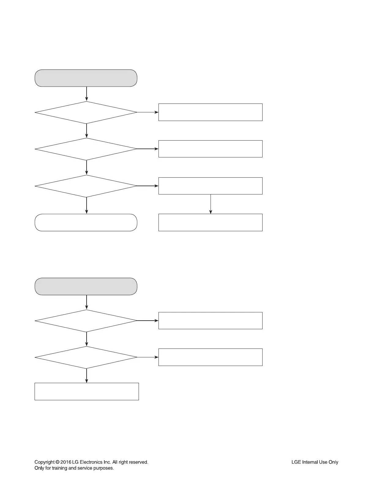
Steps for accessing and modifying EEPROM settings, including a flowchart.
Instructions for downloading firmware updates via USB for audio and other programs.
Step-by-step guide for updating firmware over the air using a smartphone app.
Technical details of the product, including power requirements, dimensions, and operating conditions.
Diagrams showing component layouts and assemblies for various parts of the unit.
Exploded view of the cabinet and main frame components.
Exploded view of the CD mechanism deck.
Diagram showing packing materials and accessories.
Exploded views of the front and subwoofer speaker units.
Troubleshooting guides for common operational faults like no power, no audio, or boot issues.
Guide for diagnosing electrical faults, including SMPS and system part issues.
Oscilloscope waveforms for critical check points like DSP, PWM, Servo, and motor drivers.
Diagram showing component interconnections and signal paths.
High-level block diagrams of system architecture and SMPS unit.
Table of specified and measured capacitor voltages for SMPS and Main boards.
Diagrams showing the layout of SMPS, Main, Front, and Front Control PCBs.
Step-by-step instructions for disassembling the deck mechanism, including cover, tray, and motor.
Steps to remove the top cover of the deck mechanism.
Steps to remove the clamp assembly from the deck mechanism.
Steps to remove the tray disc from the deck mechanism.
Steps to remove the pick-up assembly from the deck mechanism.
Steps to detach the base up/down unit from the base main.
Steps to remove the deck PCB assembly.
Steps to detach the motor assembly from the base main.
Exploded view diagram of the deck mechanism components.