Page 16 / 60 Section 3. Controls and connections
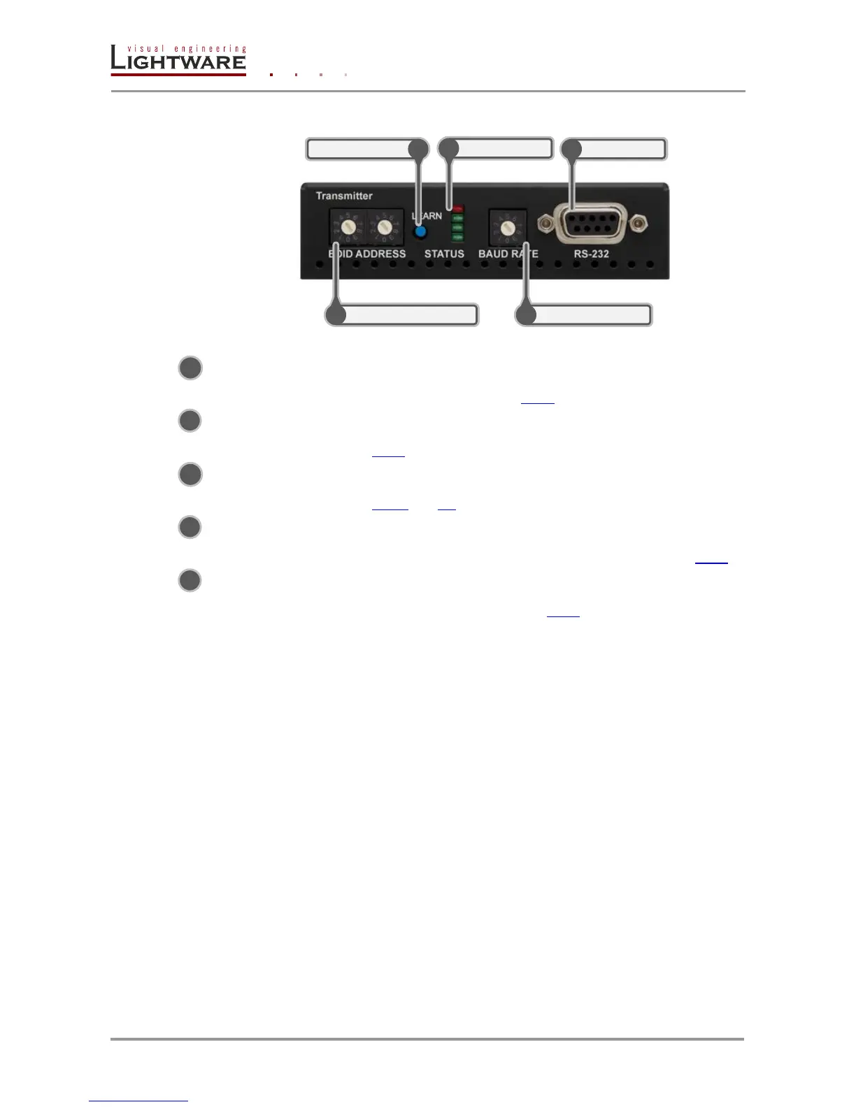
3.5. HDMI-OPT-TX100R front view
Figure 3-3. Front view
Status LEDs The LEDs give feedback about the state of units and video
signal. For more information about names and meanings of the
Status LEDs see chapter 4.4.1.
LEARN button Toggles the LED functions between PRIMARY (SOLID) and
SECONDARY (BLINKING). For more information see chapter
4.4.1.
RS-232 Port 9-pole D-sub female connector. Connect a serial cable between
the transmitter unit and the desired serial device. See sections
3.13.2 and 4.2 for more information about usage of serial port.
Rotary switches The rotary switches select one of 99 addresses. EDID
memories #1..#50 contain factory presets and #51..#99 are
user programmable. For more information, see chapter 4.4.3.
Baud Rate Rotary The rotary switch selects one of 5 speeds of the serial
communication (#0..#4) or the Software Control mode (#9). For
more information see chapter 4.2.4.
Info: Use a flat head screwdriver that fits into the rotary switches’ actuator. Avoid the use of
keys, coins, knives and other sharp objects because they might cause permanent
damage to the rotary switches.
 Loading...