Page 18 / 60 Section 3. Controls and connections
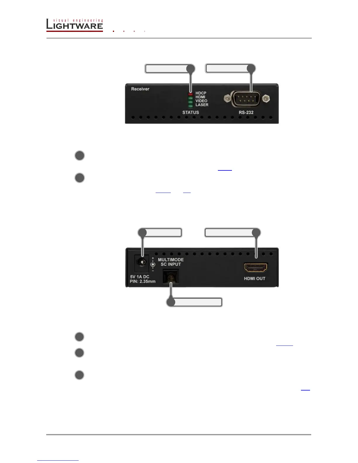
3.7. HDMI-OPT-RX100R front view
Figure 3-5. Front view
Status LEDs The LEDs give feedback about the state of units and video
signal. For more information about names and meanings of the
Status LEDs see chapter 4.4.1.
RS-232 Port 9-pole D-sub male connector. Connect a serial cable between
the transmitter unit and the desired serial device. See sections
3.13.2 and 4.2 for more information about usage of serial port.
3.8. HDMI-OPT-RX100R rear view
Figure 3-6. Rear view
HDMI OUT Connect one HDMI cable between the receiver unit and the
display device. For more information see chapter 3.13.1.
SC Fiber Input Connect a multimode single fiber optical cable between the
receiver unit and the transmitter unit (or a Lightware Hybrid
Modular Matrix equipped with optical output card).
DC +5V in Connect the output of the supplied +5V DC power adaptor.
CAUTION! Warranty void if damage occurs due to use of a
different power source. For more information see chapter 4.3.
 Loading...