35 Series-HST, Model - 3535, 4035, 4535 & 5035
52
A
B
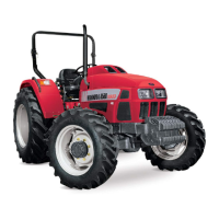
Three Point Linkage
Adjustable Lift Rod RH
Use turn handle (A) on the adjustable lift rod to raise or
lower the Telescopic Lower Link for side-to-side leveling of
implement with respect to ground.
1. Release the levelling gear box operating lever (A) out
locking clip (B).
2. Rotate turn handle (A) clockwise to raise the lower link
or anti-clockwise for lowering.
3. After adjustment, make sure turn handle is secured with
the locking clip. Always transport the implement with
turn handle in this position.
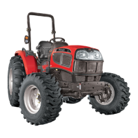
Lateral Stabilizers
These are provided for adjustment of width between two
lower links according to varying implement spans.
These enable to keep the implement in either FIXED or
FLOATING position.
Placing the locating pin in (C) position shall keep the
stabilizer and implement in “Fixed” position.
Placing the locating pin in (D) position shall keep the
stabilizer and implement in “Float” position.
We recommend to use the fixed position while transporting
the implement.
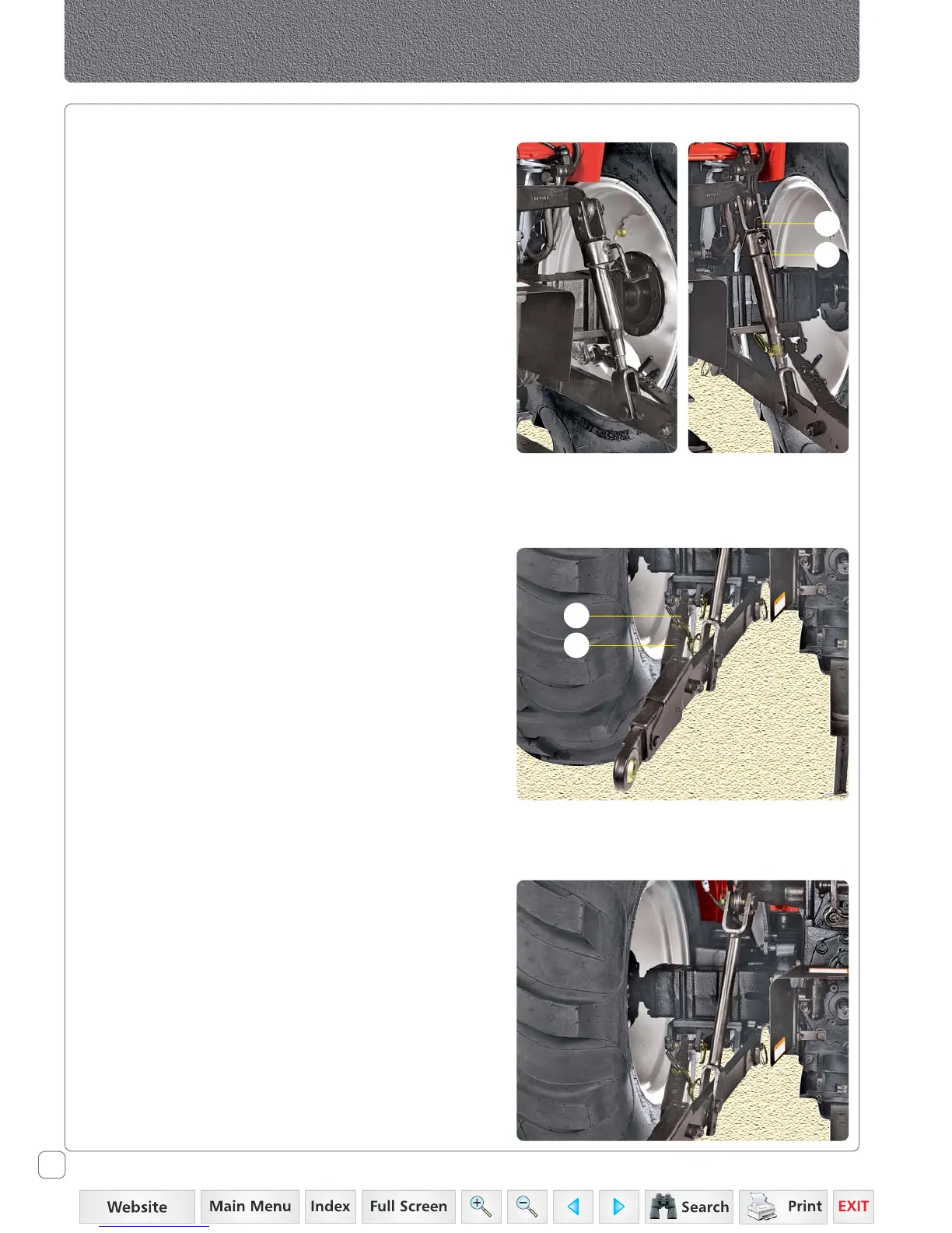
Lift Rod L.H.
There are two holes provided on the lift rod LH. This is
provided to adjust the height of lower link LH as desired.
To adjust the height of the lower link, remove locking pin
out of the lift rod-Lower link and adjust the height by
putting the locking pin in the required hole as needed.
Locked Unlocked
D
C
 Loading...