35 Series-HST, Model - 3535, 4035, 4535 & 5035
54
Attachments
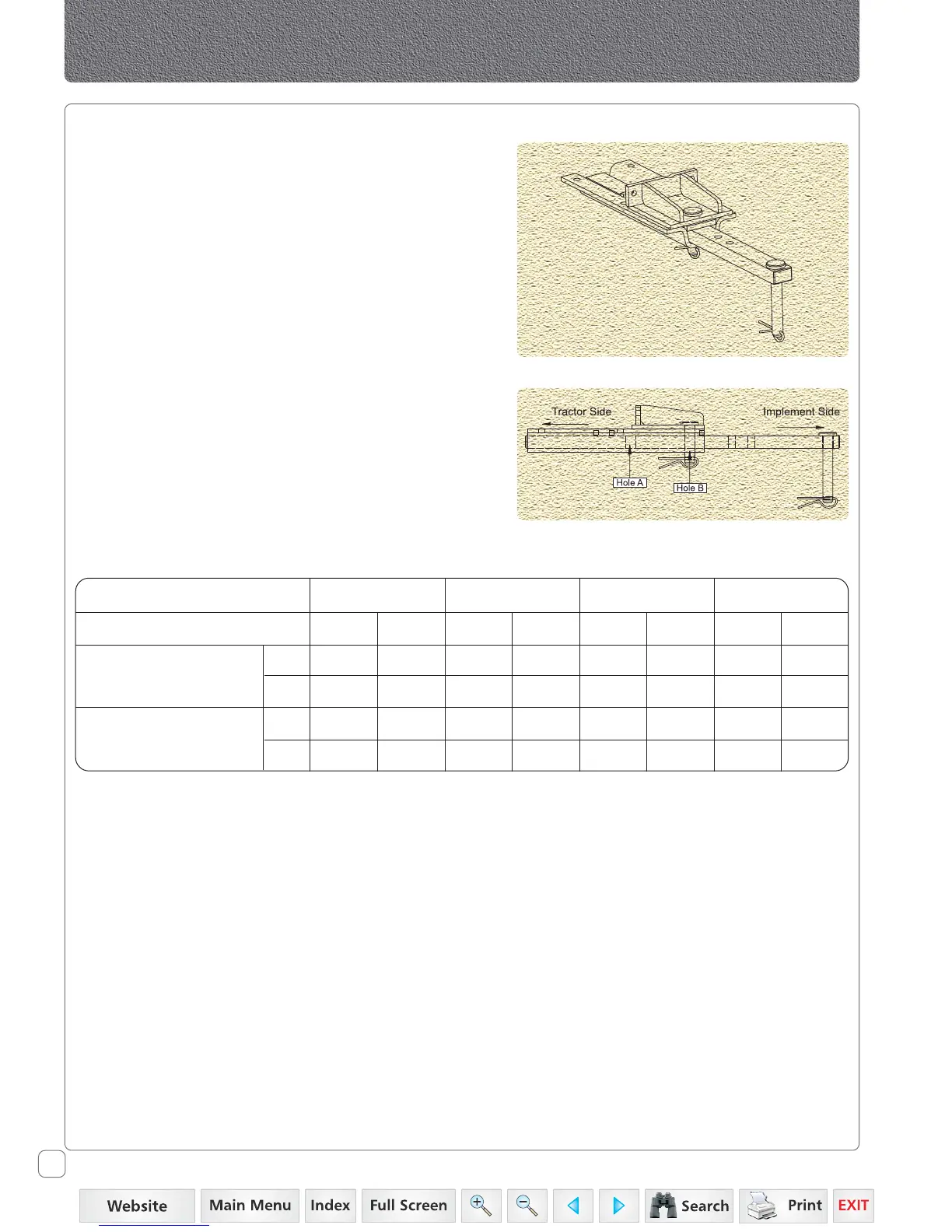
Drawbar
There are two holes on the drawbar for attaching the
drawbar to the drawbar bracket.
1. For regular PTO driven implement and for maximum
traction while pulling the trailer lock the drawbar to the
drawbar bracket using hole B.
2. Lock the drawbar to the drawbar bracket in the hole A
for a position intended for special PTO driveshaft
condition where equal angularity of driveshaft joints
cannot be obtained using regular position.
Tractor Model 3535 4035 4535 5035
Drawbar Hole Positions A B A B A B A B
Dist. of Implement Pin
mm 500 350 500 350 500 350 500 350
Hole from PTO shaft end
inch 19.69 13.78 19.69 13.78 19.69 13.78 19.69 13.78
Max. Vertical
Kg 306 383 338 422 376 470 415 519
Load On Drawbar
Lb 675 844 743 929 829 1036 914 1143
 Loading...