35 Series-HST, Model - 3535, 4035, 4535 & 5035
79
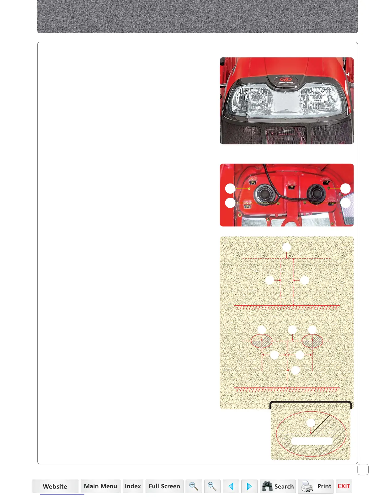
Head lamp adjustment
1. Tighten screws (W), (X), (Y) and (Z) fully.
2. Turning screw (W) & (Y) in anti-clockwise direction will
raise the Beam.
3. Turning screw (X) & (Z) in anti-clockwise direction will
lower the Beam and move towards Right of the
operator’s view.
Aiming Head Lamps
1. Park tractor on level ground, with lights 9.8 ft. (3 m)
from a wall.
2. Measure centre of head lamp to ground height (A).
Place a strip of masking tape (B) on the wall at the same
height.
3. Place a piece of tape, folded in the middle to make a
point, on the top front center of the Hood.
4. Using the Hood tape as a guide, sight across steering
wheel and Hood to locate tractor center line. Mark
tractor center line (C) on wall.
5. From tractor center line (C), mark a point (D) 5 inch.
(127 mm) out in each direction.
6. Turn light switch to dim position.
7. Locate point (E) of bright light projected by each lamp
by adjusting screws (W), (X), (Y) and (Z) as required.
Cover other lamps, if necessary.
E
Bright Light Area
C
DD
BBE
AC
B
Head Lamp Adjustment
W
X
Y
Z
 Loading...