Repair
P 13/ 19
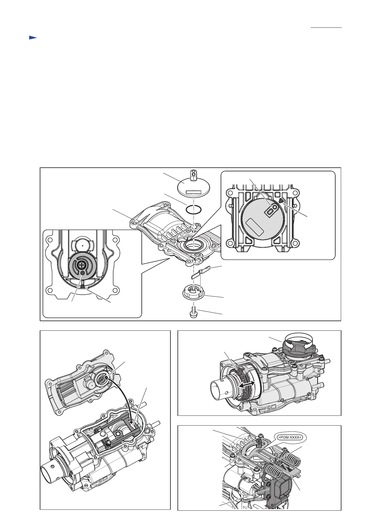
(10) When Change lever section is disassembled;
• fit the projection of Leaf spring into the groove on Link lever. (Fig. 31)
• reassemble the components to Crank cap and Housing cover by M4x10 Pan head screw with care to the directions
(Fig. 31)
• assemble Crank cap to Crank housing while aligning the pin of Crank cap to the opening of Link guide (Fig. 32).
(11) In the process of reassembling, i.e., as drawn in Fig. 33, set Change lever section in place temporarily and turn
Change lever counterclockwise and clockwise to check that Driving sleeve moves back and forth.
(12) When Switch case set and Control plate are set in place;
• while facing the mark of “>POM-xxxx<” on Control plate to the upper side, pass the projection of Crank lever
through the rounded opening of Control plate.
• pass the square pin of Switch lever C through the long opening of Control plate.
Crank lever
O ring 18
Projection of Leaf spring
Groove of Link lever
M4x10 Pan head screw
Driving sleeve
Long opening
of Control plate
Change lever
Crank cap
[3] DISASSEMBLY/ASSEMBLY
[3]-3. Crank housing, Cylinder, Counter weight (cont.)
Fig. 31
Fig. 32 Fig. 33
Fig. 34
Projection of Crank lever
Mark on
Crank cap
Projection of
Crank lever
Rounded opening
of Control plate
Switch case set
Pin of Link lever
Pin of Link lever
Opening of Link
guide
Mark on the reverse
side of Crank cap
Square pin of
Switch lever C

 Loading...