[3] DISASSEMBLY/ASSEMBLY
[3]-3. Crank housing, Cylinder, Counter weight
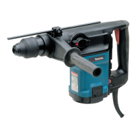
(3) Remove Drive sleeve by pushing the end of Link plate from Crank side. Then, remove Guide ring. (Fig. 12)
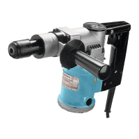
(4) Put three pieces of 1R350 on Crank housing complete, and then remove Cylinder from Crank housing with 1R213
through the holes of the three pieces of 1R350. (Fig. 13)
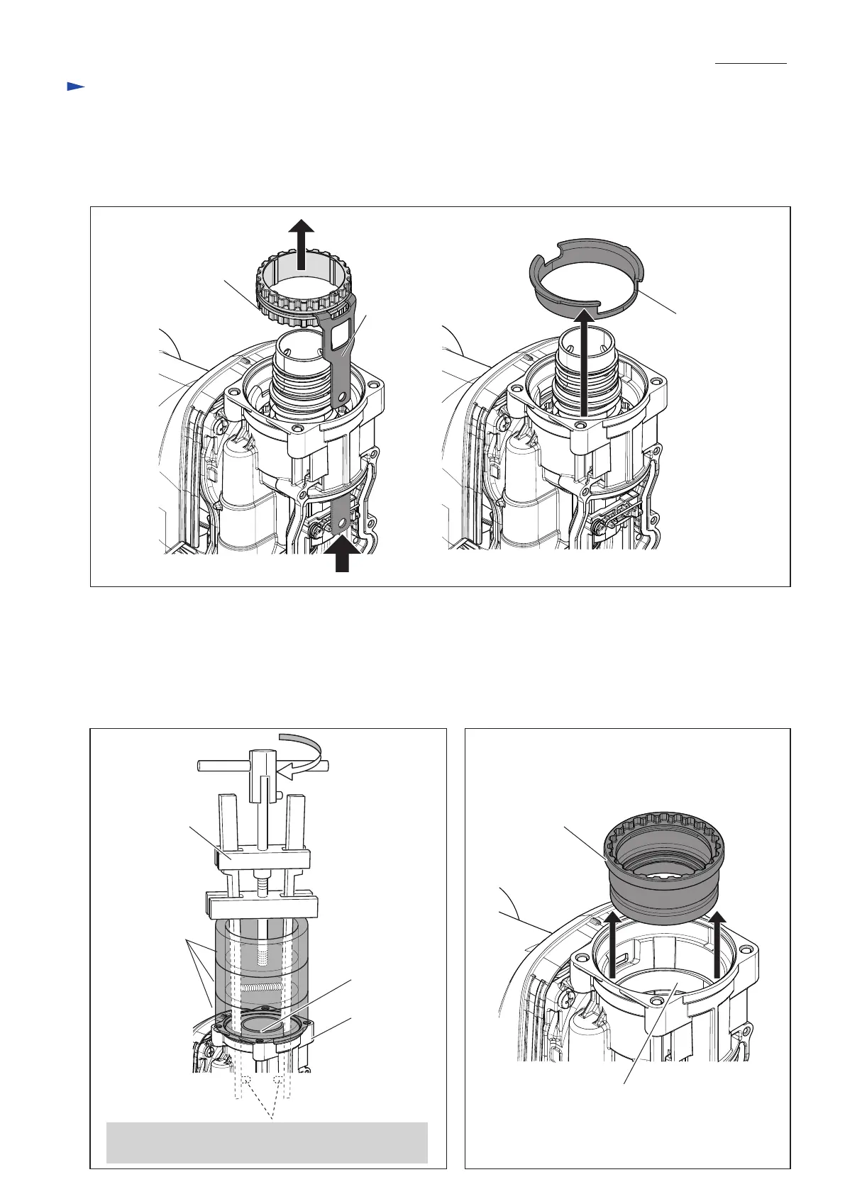
(5) Remove Spiral bevel gear 26 from Crank housing carefully so as not to be tilted. (Fig. 14)
When Spiral bevel gear 26 is tilted in Crank housing in the disassembly process;
- it is impossible to remove Spiral bevel gear 26.
- Plane bearing 54 in Crank housing is harmed.
Fig. 13 Fig. 14
Fig. 12
Repair
P 8/ 19
Guide ring
Link plate
Driving sleeve
1R350
(3 pcs.)
1R213
Crank housing
complete
Spiral bevel gear 26
Plane bearing 54
(The component of Crank housing)
Cylinder
Insert the two pins of 1R213 into the holes of Cylinder,
and then turn the handle of 1R213

 Loading...