P 7/ 19
DISASSEMBLING
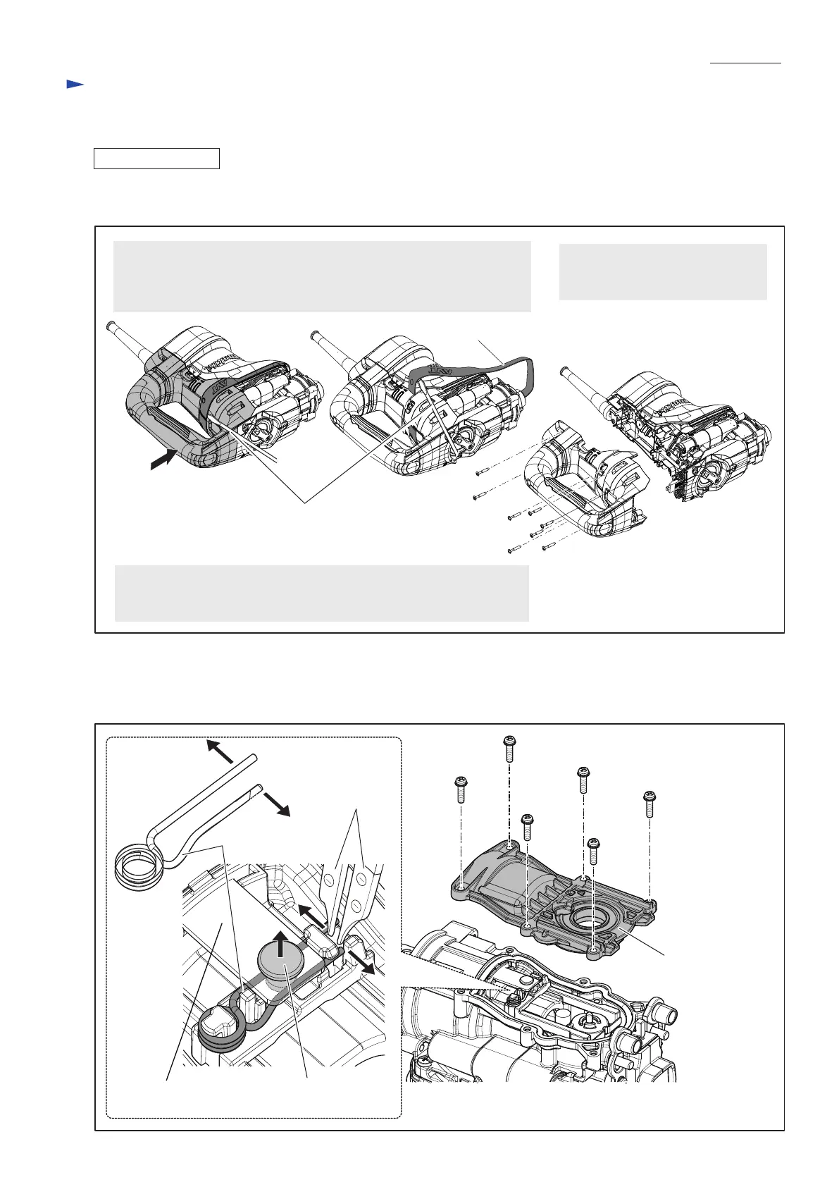
Fig. 10
Fig. 11
(1) After removing Barrel section as drawn in Fig. 6, disassemble Handle section as drawn in Fig. 10.
(2) Remove six M4x16 Pan head screws and Crank cap.
While expanding the ends of Torsion spring 7 with 1R003, remove Flat fillister head pin 6 on Link plate. (Fig. 11)
As for HR4003C,
• the removal precess of Guard 40 can be skipped.
• Disassemble Handle section by unscrewing six 4x25 Tapping screws.
1. Reserve the insertion slit for a slotted screwdriver between Guard 40
and Handle base for HR4013C by pressing Handle section toward
Crank housing side.
And remove Guard 40 by prying it up with a slotted screwdriver.
2. Disassemble Handle section for
HR4013C by unscrewing eight
4x25 Tapping screws.
Guard 40
Slotted screwdriver
[3] DISASSEMBLY/ASSEMBLY
[3]-3. Crank housing, Cylinder, Counter weight
Repair
4x25 Tapping screw
(8 pcs.)
Torsion spring 7
1R003
Flat fillister head pin 6Link plate
M4x16 Pan head screw (6 pcs.)
Crank cap

 Loading...