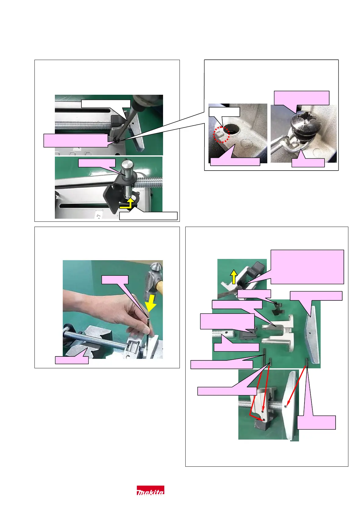
EasyManuals Logo

Makita LW1401 Technical Information

Makita LW1401
15 pages
To Next Page IconTo Next Page
To Previous Page IconTo Previous Page
Page #8 background imageLoading...
Page #8 background image
5-3-4 Vise Section
5-3-4-1 Disassembling
Fig. 4-1
1) Remove two M8x30 PH Screw (70) with No.3
phillips Bit and Cordless impact driver. Remove Pin
16 (89) by sliding Vise Ass’y (119).
No.3 phillips Bit
M8x30 PH Screw (70)
(2 pcs.)
Pin 16 (89)
Remove at this point.
3) Chain should be fixed to Screw guide (67) to
clamp main body as the below photos.
Projection
Screw guide (67)
Chain (64)
M8x30 Pan head
Screw (70)
Fig. 4-3
3) Put Vise on IR258. Remove Spring pin 5-36 (68) and
Spring pin 4-16 (69) with1R308 and 1R309.
IR 309
IR 258
Fig. 4-4
4) The component of Vise section (119) is as follows.
Remove Plate (66) by
prying it off with a slotted
screwdriver.
Note: Plate (66) is
non-directional
Plate (66)
Screw guide (67)
Handle 120 (59)
Vise screw (60)
Vise nut (65)
Note: Directional
**Spring pin 5-36 (68)
*Spring pin 4-16 (69)
* with 1R308 to assemble
** with 1R309 to assemble
Fig. 4-2 (only LW1401)
**Spring pin
5-20 (58)
Makita Corporation 8 / 15

Other manuals for Makita LW1401

Questions and Answers:

Question and Answer IconNeed help?

Do you have a question about the Makita LW1401 and is the answer not in the manual?

Makita LW1401 Specifications

General IconGeneral
No Load Speed3, 800 RPM
Amperage15 A
Voltage120 V
Blade Diameter14 in
Cutting Capacity (Round)127 mm
Arbor Size1 in
Max Cutting Depth at 90°127 mm

Related product manuals