1
2
3
4
Setting valve clearance
84
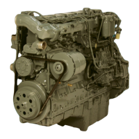
Fig. 1
Remove cylinder head cover (13mm).
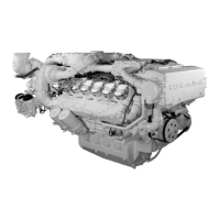
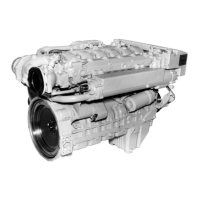
Figs. 2 and 3
Use barring device to turn engine so that the pis-
ton in the cylinder to be set is at TDC and the two
valves are closed. At this point both inlet and ex-
haust valves will be open i.e. valves overlap.
Note:
As far as possible turn engine only in direc-
tion of rotation (anti-clockwise as seen when
looking at the flywheel) in order to prevent
the direction of rotation of the raw water
pump impeller being reversed.
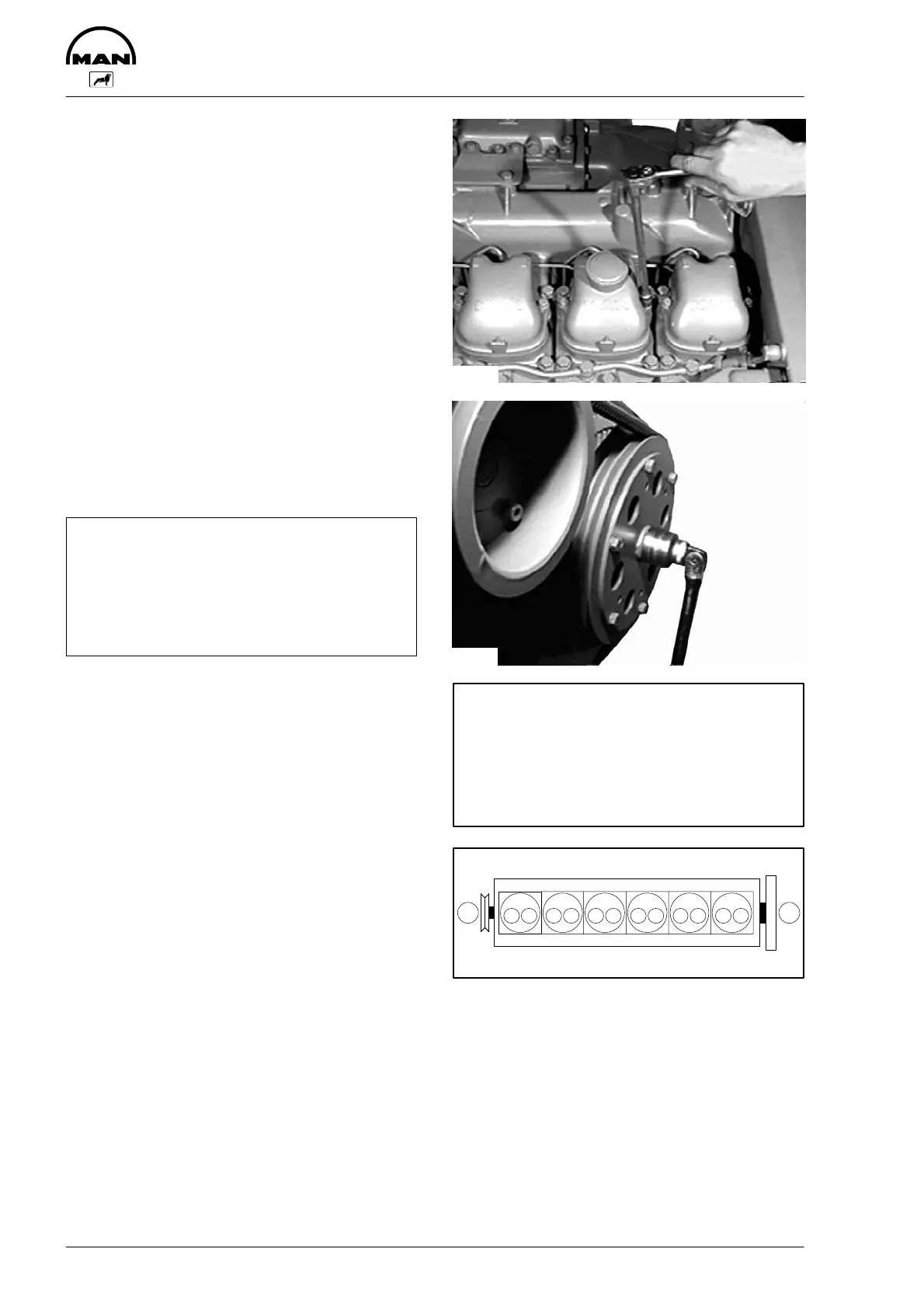
Fig. 4
Arrangement of cylinders and valves
I Engine front end
II Flywheel side
A Exhaust valve
E Inlet valve
3389
3390
Valves are in crossover in cylinder
1
5 3 6 2 4
6
2 4 1 5 3
Set valves in the cylinder
I
II
EA EA EA EA EA EA
123456
3607
 Loading...