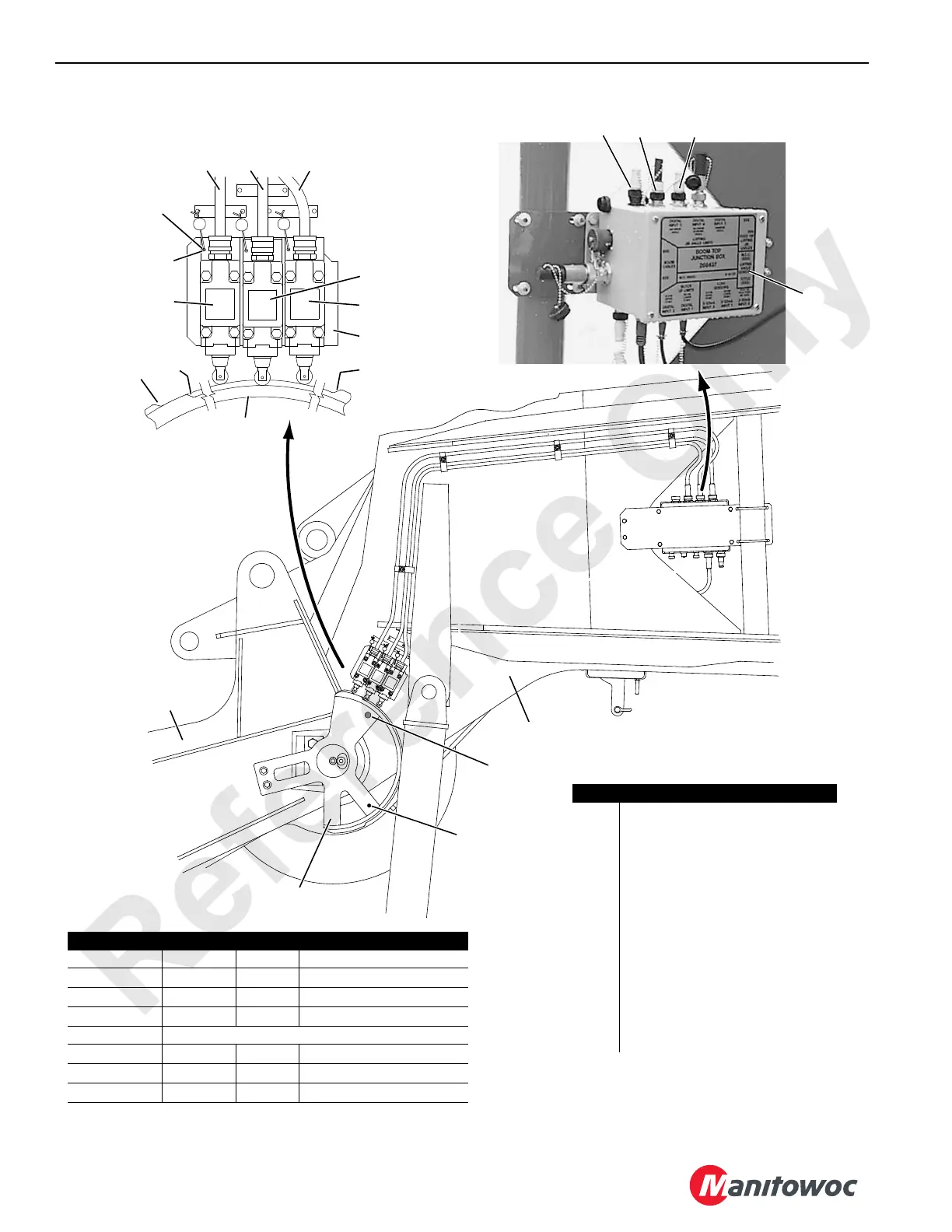
FIGURE 6-1
Lead Wire Seal
and Roll Pin
(Typical)
9
3
6
2
10
5
4
12 13 11
Left Side of Boom
P1518
Boom Top
7
8
In Hole A
1
13
11
12
LIMIT SWITCH WIRING
Cord Terminal Wire System Operation
P1-1 WHT S1-22 8B
12 Volts DC
P1-2 BLK S1-21 89W1
MAX UP 1
P2-1 GRN S2-21 89W2
MAX UP 2
P2-2 BLK Not Used
P2-3 WHT S2-22 8B
12 Volts DC
P3-1 WHT S3-22 8B
12 Volts DC
P3-2 BLK S3-21 89S1
MAX DOWN
2
Hole B
14
Jib Butt
A1205
Item Description
1 Junction Box
2 Actuator
3 Limit Switch — MAX UP 1
4 Limit Switch — MAX UP 2
5 Limit Switch — MAX DOWN
6Cam — MAX UP 1
7Cam — MAX UP 2
8Cam — MAX DOWN
9 Spacer (each limit switch)
10 Mounting Bracket
11 MAX DOWN Electric Cord
12 MAX UP 1 Electric Cord
13 MAX UP 2 Electric Cord
14 Alignment Pin

 Loading...


