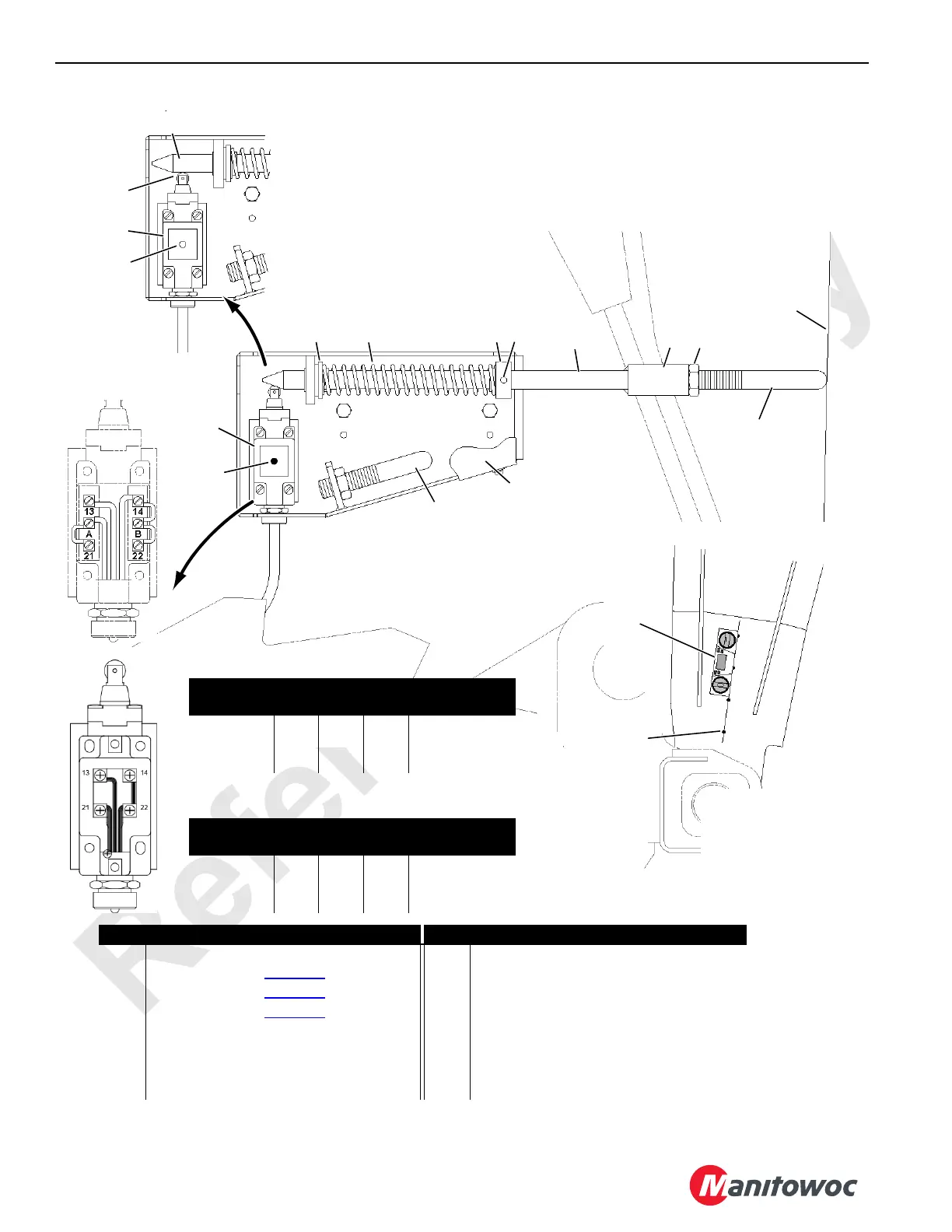
FIGURE 6-4
VIEW A
SWITCH
OPENED
Item Description Item Description
1 Boom Butt 7 Spring Washer
2a Adjusting Rod (see Figure 6-3
)8Spring
2b Adjusting Rod (see Figure 6-3
) 9 Spring Washer
2c Adjusting Rod (see Figure 6-3
) 10 Dowel Pin 1/4 in (6,35 mm) Diameter
3 Jam Nut 11 Actuator Rod
4 Coupling 12 Punch Marks
5 Limit Switch 13 Digital Level
6Cover
Roller
Over-Travel
LED
ON
7 8 9 10
11
4
2a,
3
LED
OFF
5
5
6
VIEW B
SWITCH
CLOSED
11
1
Left Leg
VIEW C
Right Outboard Leg
13
12
Limit Switch Wiring Past Production
Receptacle
Switch
Terminals
Function
1 (green) 22
B14
Max Angle
2 (black) A
13
LED
3 (white) 21 12 VDC Supply
2b,
or
2c
2a,
2b,
or
2c
STORED
Limit Switch Wiring Current Production
Receptacle
Switch
Terminals
Function
1 (green) 22
14
Max Angle
2 (black)
13
3 (white) 21 12 VDC Supply

 Loading...


