SETUP AND INSTALLATION 999 LUFFING JIB OPERATOR MANUAL
4-4
Published 05-15-17, Control # 043-09
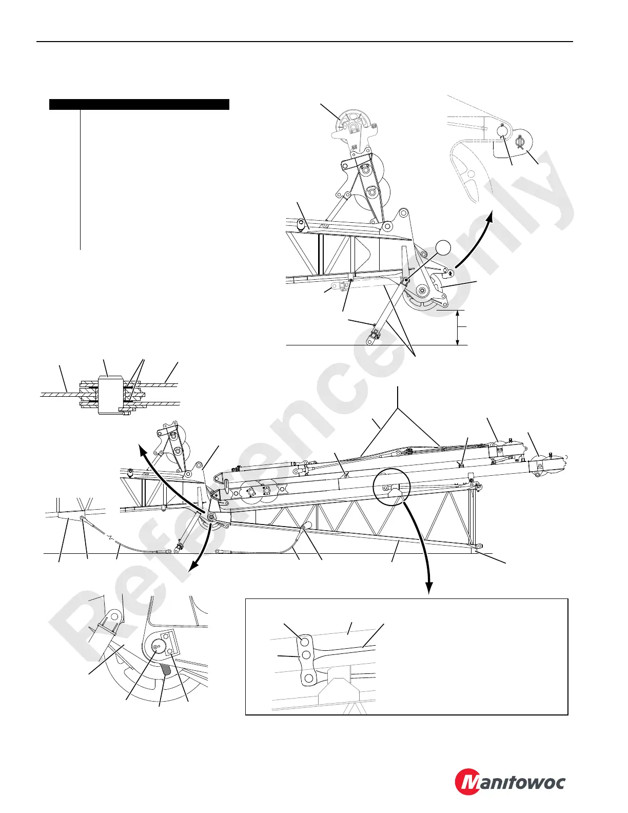
FIGURE 4-3
Item Description
1 Guide Roller
2 Shaft with Cotter Pins
3 Storage Pin with Snap Pins
4 Pin with Cotter Pins
5 Lifting Slings
6 Lifting Lug (4 places)
7Pin
8 Keeper Plate with Screws and Lock
Washers
9Shims
10 Jib Stop Pendant 24 ft, 1 in (7,3 m)
11 Pin with Cotter Pin
12 Jib Stop Pendant 9 ft, 6-1/2 in (2,9 m)
Jib Stop Strut
Assembly Stored
4
3
26 in (0,7 m)
VIEW B
A1204
7
8
Jib Stop
Strut Assembly
Boom Top
VIEW A
2
1
Upper Wire Rope
Guide Must Be
Removed
Lower Boom Point
Sheaves Removed
If Required
9
Jib
Butt
VIEW C
9
Boom
Butt
7
VIEW E
Jib
Butt
Boom
Butt
Jib
Butt
Jib
Strut
Main
Strut
Boom
Top
Boom
Top
6
6
12 1111 10
5
Blocking
6 in (152 mm)
High
To p
Holes
Links
Straps must be connected to links as
shown. Top holes in links are provided only for
handling purposes. If it becomes necessary to
separate jib strut from butt, support links and
top straps by inserting a bar through top holes
in links and across legs of jib strut.
Jib
Strut
Top
Straps
VIEW F
VIEW B
Jib Stop
Strut Assembly

 Loading...


