Published 01-15-2016, Control # 526-01 4-13
RT540E OPERATOR MANUAL SET-UP AND INSTALLATION PROCEDURES
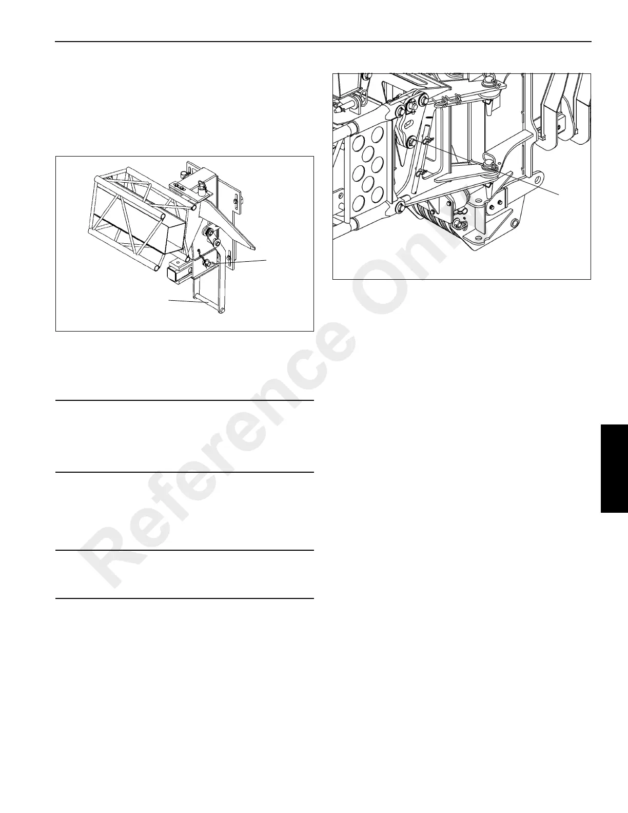
17. On the rear stowage bracket, remove the pin securing
the sliding support in the “OUT” position. Push in on the
handle (10) Figure 4-14 to push the swingaway against
the rear of the boom and disengage the swingaway
anchor fittings from the boom nose attachment lugs (9)
Figure 4-9. Install the retainer pin (11) Figure 4-14
securing the sliding support in the “IN” position.
18. Rig the boom nose and hoist cable as desired and
operate the crane using normal operating procedures.
Setting The Offset
1. Extend and set the outriggers. Swing the boom over to
the front of the crane.
2. To set the offset from zero degrees (0°) to thirty degrees
(30°), perform the following:
a. Slowly lower the boom until the tip of the swingaway
is on the ground and the pressure on the offset pin is
relieved.
b. Remove the lock pin, two washers, and offset pin
(12). Figure 4-15
c. Slowly elevate and telescope the boom at the same
time until the offset shaft takes the full load of the
swingaway.
3. To set the offset from thirty degrees (30°) to zero
degrees (0°), perform the following:
a. Slowly lower the boom until the tip of the swingaway
is on the ground and the offset pin can be installed.
b. Install the offset pin, two washers, and lock pin (12).
Figure 4-15
c. Raise the boom and operate as desired.
Changing Boom Extension From
Telescoping Type To Fixed Type
1. Erect the boom extension.
2. Position the boom to horizontal.
3. Disconnect the anti-two block cable connector from the
junction box.
4. Remove the telescoping section hitch pin and retaining
pin.
NOTE: The telescoping section weighs approximately 250
kg (551 lb).
5. Extend the telescoping section and attach an adequate
lifting device to support the telescoping section. Remove
the stop bolts from the base section and remove the
telescoping section from the base.
NOTE: The pin-on boom extension nose weighs
approximately 60 kg (132 lb).
6. Using an adequate lifting device, position the pin-on
boom extension nose in the base section and secure
with the two pins and hitch pins.
CAUTION
The mast assembly must be positioned on top of the base
section before attempting to offset the swingaway to 30
degrees. Failure to do so can cause damage to the mast
and/or swingaway adapter.
CAUTION
Do not overload the swingaway or the attachment points
when lowering the boom.
Reference Only

 Loading...


